A kind of automatic coupling device and automatic coupling method

A technology of automatic coupling and coupling devices, applied in the coupling of optical waveguides, instruments, optics, etc., can solve the problems of difficult fiber coupling and poor device consistency, and achieve the effects of good consistency, improved efficiency and accuracy

Active Publication Date: 2020-06-30
GUANGXUN SCI & TECH WUHAN
View PDF9 Cites 0 Cited by
  • Summary
  • Abstract
  • Description
  • Claims
  • Application Information

AI Technical Summary

Problems solved by technology

This solves the current technical problems that the coupling between the optical fiber and the device to be coupled is difficult and the consistency of the device is poor

Method used


Image

  • A kind of automatic coupling device and automatic coupling method
  • A kind of automatic coupling device and automatic coupling method
  • A kind of automatic coupling device and automatic coupling method

Examples


Embodiment 1

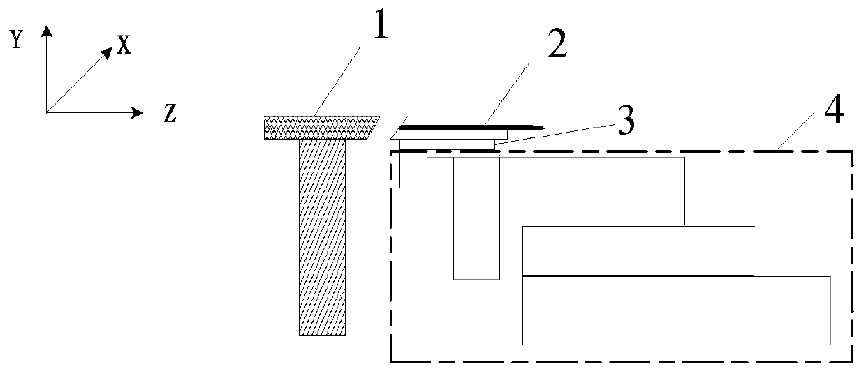
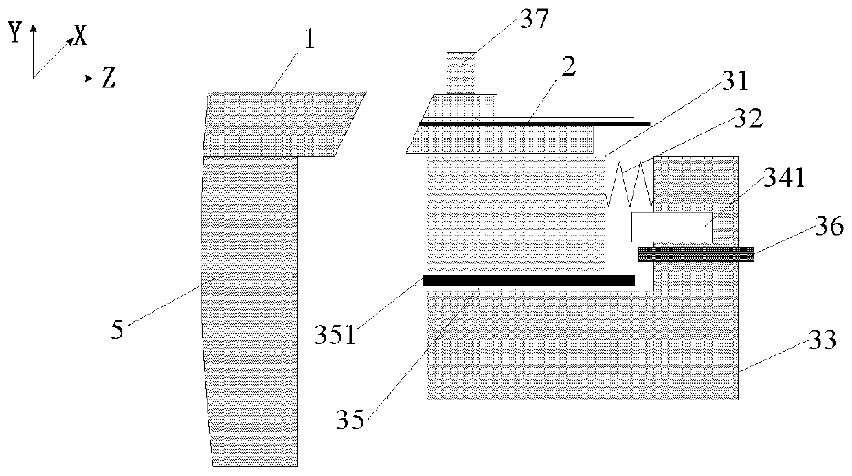
[0060] refer to figure 1 and figure 2 , the present embodiment provides an automatic coupling device, the automatic coupling device is used to couple the device to be coupled 1 and the optical fiber 2, the automatic coupling device includes: a clamping mechanism 3 and an adjusting mechanism 4, and the clamping mechanism 3 is arranged on On the adjustment mechanism 4.

[0061] In this embodiment, the clamping mechanism 3 includes a sliding platform 31 and an elastic member 32 , one end of the elastic member 32 is connected to the sliding platform 31 . Wherein, the elastic member 32 can be a spring, and the elastic force of the spring should not be too large, otherwise it will cause edge collapse of the device 1 to be coupled. In an optional embodiment, the maximum load of the spring is 4N, and the spring constant is greater than 1.0N / mm. In the actual design process, the friction force and other factors when the slide table 31 slides can be considered comprehensively, and a ...

Embodiment 2

[0101] Different from Embodiment 1, there is another optional solution in this embodiment, which is to detect the compression state of the elastic member 32 so that the adjustment mechanism 4 can adjust the posture of the clamping mechanism 3 . Such as Figure 12 As shown, the clamping mechanism 3 also includes a pressure sensor 342, the pressure sensor 342 is arranged on the base 33, and the other end of the elastic member 32 is connected to the pressure sensor 342; the pressure sensor 342 It is used to detect changes in the elastic force of the elastic member 32 to trigger the adjustment mechanism 4 to adjust the posture of the clamping mechanism 3 .

[0102] In this embodiment, the pressure sensor 342 is used to detect the change of the elastic force of the elastic member 32 to determine the compression state of the elastic member 32 and determine the sliding table 31 (such as Figure 12 Shown, the distance between the slide table 31 right end surface) and the base 33 and ...

Embodiment 3

[0108] An embodiment of the present invention provides an automatic coupling method, and the automatic coupling method is applicable to the automatic coupling device in Embodiment 1 or Embodiment 2 above.

[0109] Such as Figure 14 As shown, the automatic coupling method of the present embodiment includes the following steps:

[0110] Step 10: Clamp the optical fiber on the clamping mechanism, and fix the device to be coupled on the fixed platform.

[0111] Step 11: adjusting the posture of the clamping mechanism through an adjusting mechanism, and detecting the compression state of the elastic member, so that the end face of the optical fiber is parallel to the end face of the device to be coupled.

[0112] In a specific application scenario, the sensor acquires the change of the compression state of the elastic member to monitor the contact state between the optical fiber and the device to be coupled. The control system controls the movement of the adjustment mechanism ac...


PUM


Abstract

The invention discloses an automatic coupling device and an automatic coupling method. The automatic coupling device is used for coupling a device to be coupled and an optical fiber and comprises a clamping mechanism and an adjusting mechanism, wherein the clamping mechanism is arranged on the adjusting mechanism; the clamping mechanism comprises a sliding table and an elastic piece, and one end of the elastic piece is connected with the sliding table; the clamping mechanism is used for clamping the optical fiber; the adjusting mechanism is used for adjusting the posture of the clamping mechanism; and in the process that the adjusting mechanism adjusts the posture of the clamping mechanism, a contact state between the optical fiber and the device to be coupled is monitored according to thechange of the compression state of the elastic piece, so that the end face of the optical fiber is parallel to the end face of the device to be coupled. The invention has the advantages that by adopting the elastic piece, the sliding table can be prevented from sliding backwards under the action of gravity in the process of adjusting the parallelism of the end face, so that the displacement change of the sliding table can be monitored more accurately, the posture of the clamping mechanism can be effectively adjusted, the end face of the optical fiber is parallel to the end face of the deviceto be coupled, and the consistency is better.

Description

technical field [0001] The invention belongs to the technical field of optical device manufacturing, and more specifically relates to an automatic coupling device and an automatic coupling method. Background technique [0002] Passive devices based on Planar Lightwave Circuit (abbreviated as PLC) technology include: arrayed waveguide grating (abbreviated as AWG) and array optical attenuator, etc. The advantages of integration and mass production are widely used in the field of optical communication. Due to the narrow channel of arrayed waveguide devices, the normal width of the channel is 4.4μm*4.4μm, the number of channels is large (typical values ​​are 4CH, 24CH, 48CH or 96CH, etc.), and the channel spacing is small (typical values ​​127μm, 254μm), resulting in It is difficult to couple in the production process, and the coupling efficiency is low. In addition, arrayed waveguide devices are coupled with Fiber Array (abbreviated as FA). For ribbons made of single-mode opt...

Claims


Application Information

Patent Timeline
Patent Type & Authority Patents(China)
IPC IPC(8): G02B6/30G02B6/36
CPCG02B6/30G02B6/3616
Inventor 楚劲草谭书伟尹华林周园刘欢李礼
Owner GUANGXUN SCI & TECH WUHAN
Why Eureka
Try Eureka