Optical fiber storage device

A storage device and optical fiber technology, applied in the field of communication, can solve problems such as long troubleshooting time, affecting optical fiber links, messy fiber cores, etc., and achieve high troubleshooting efficiency, low probability of misoperation, and clear optical fiber identification

Pending Publication Date: 2019-07-26
GUIZHOU POWER GRID CO LTD
View PDF11 Cites 0 Cited by
  • Summary
  • Abstract
  • Description
  • Claims
  • Application Information

AI Technical Summary

Problems solved by technology

The problem existing in the existing optical fiber storage device is that all the fiber cores are coiled on one fiber coil twisted column, the front and the rear are always coiled together, and the old fiber is pressed inside by the new fiber coil, resulting in the following problems:
[0003] 1) The fiber core is messy, and it is more difficult to exit the fiber core after multiple fiber coils. Once the business is transferred or the troubleshooting takes a long time;
[0004] 2) In addition, it is difficult to find the fiber core, and the fiber core cannot be cleaned out quickly and accurately, resulting in difficulty in installation;
[0005] 3) The logo can only be marked at both ends, and the logo in the disk fiber is easily blocked, resulting in misoperation and interruption of the running channel;
[0006] 4) It cannot be operated independently. Once there is a failure or there is a cutover transfer, it will be very troublesome, and even affect the original operation of the optical fiber link

Method used


Image

  • Optical fiber storage device
  • Optical fiber storage device
  • Optical fiber storage device

Examples


Embodiment Construction

[0041] Below in conjunction with accompanying drawing and specific embodiment the invention is further introduced:

[0042] refer to Figure 1 to Figure 4 , an optical fiber storage device,

[0043] include:

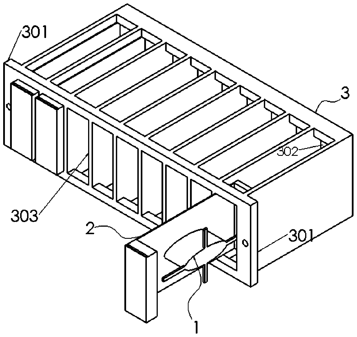
[0044] winch reel 1;

[0045] The optical fiber storage device also includes:

[0046] Storage box 2 and storage rack 3;

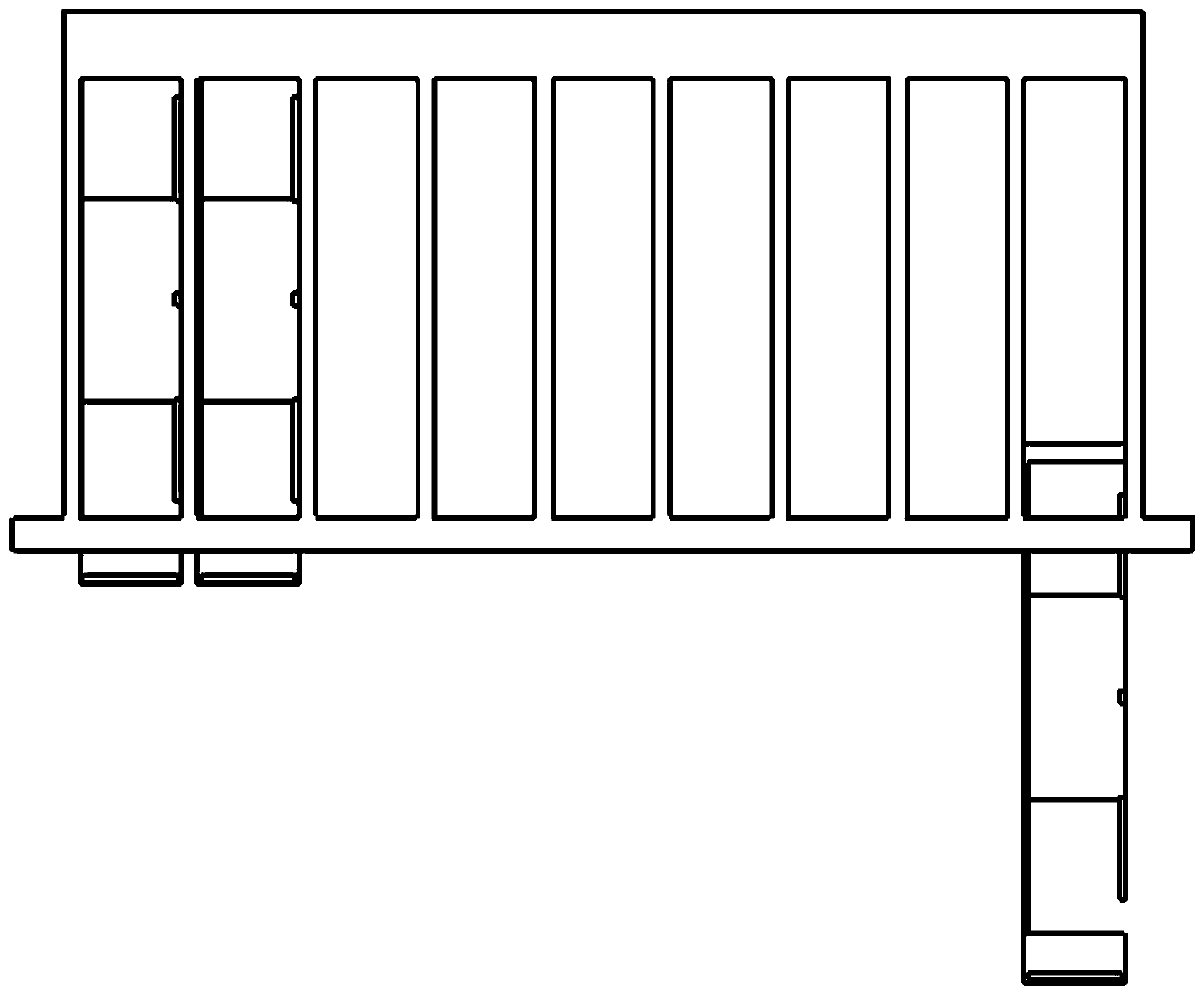
[0047] The upper and lower surfaces of the storage box 2 are open, and the twisted coil 1 is welded or bolted inside the storage box 2;

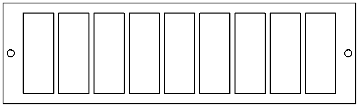
[0048] The storage frame 3 is provided with a storage box slot 303 that matches the storage box 2, and the upper and lower surfaces of the storage box slot 303 are open;

[0049] The left and right sides of the front part of the storage rack 3 are provided with mounting plates 301, and screw holes are provided on the mounting plate 301;

[0050] The storage box 2 is installed on the storage frame 3 through the storage box slot 303 .

[0051] In the present invention, the optical fibers of different routes ar...


PUM


Abstract

The invention discloses an optical fiber storage device. The device comprises a winch, a storage box and a storage frame; the upper and lower surfaces of the storage box are opened; the winch is fixedly connected in the storage box; a storage box slot matched with the storage box is formed in the storage frame; the upper and lower surfaces of the storage box slot are opened; mounting plates are arranged on the left and right sides of the front part of the storage frame; screw holes are formed in the mounting plates; and the storage box is mounted on the storage frame through the storage box slot. The device is capable of solving the existing problems that 1) the fiber cores are disordered so that business transfer or troubleshooting time is relatively long; 2) the fiber cores are relatively difficult to find so that the mounting is difficult; 3) identifiers only can be marked at two ends and the identifiers in the fiber cores are easy to be blocked so that mistaken operations are easyto cause; and 4) the fiber cores cannot be operated independently and separately so that troubles are caused once faults or cutting transfer jobs occur and even the original optical fiber link operation is influenced.

Description

technical field [0001] The invention relates to the field of communication technology, in particular to an optical fiber storage device. Background technique [0002] The existing optical fiber storage device is a twisted wire reel, which only includes a twisted wire post and a stopper. One end of the twisted wire post is fixedly connected to the optical fiber installation cabinet, and the other end is fixedly connected to the stopper. When in use, the optical fiber is wound on the twisted wire. The optical fiber can be stored on the column. The problem existing in the existing optical fiber storage device is that all the fiber cores are coiled on one fiber coil twisted column, the front and the rear are always coiled together, and the old fiber is pressed inside by the new fiber coil, resulting in the following problems: [0003] 1) The fiber core is messy, and it is more difficult to exit the fiber core after multiple fiber coils. Once the business is transferred or the t...

Claims


Application Information

Patent Timeline
Patent Type & Authority Applications(China)
IPC IPC(8): G02B6/44
CPCG02B6/4457
Inventor 滕清松谢扬飞徐明伟罗国忠胡盛李朝磊
Owner GUIZHOU POWER GRID CO LTD
Why Eureka
Try Eureka