Process and device for controlling vehicle braking system

A technology of automobile braking and control signals, which is applied to the safety device of the power plant control mechanism, the brake transmission device, the control valve and the air release valve, etc., and can solve the problems such as the deterioration of the dynamic characteristics of the pressure change

Inactive Publication Date: 2003-02-05
ROBERT BOSCH GMBH
View PDF4 Cites 0 Cited by
  • Summary
  • Abstract
  • Description
  • Claims
  • Application Information

AI Technical Summary

Problems solved by technology

Therefore, under some conditions of use, the dynamic characteristics of the pressure change will be deteriorated

Method used


Image

  • Process and device for controlling vehicle braking system
  • Process and device for controlling vehicle braking system
  • Process and device for controlling vehicle braking system

Examples


Embodiment Construction

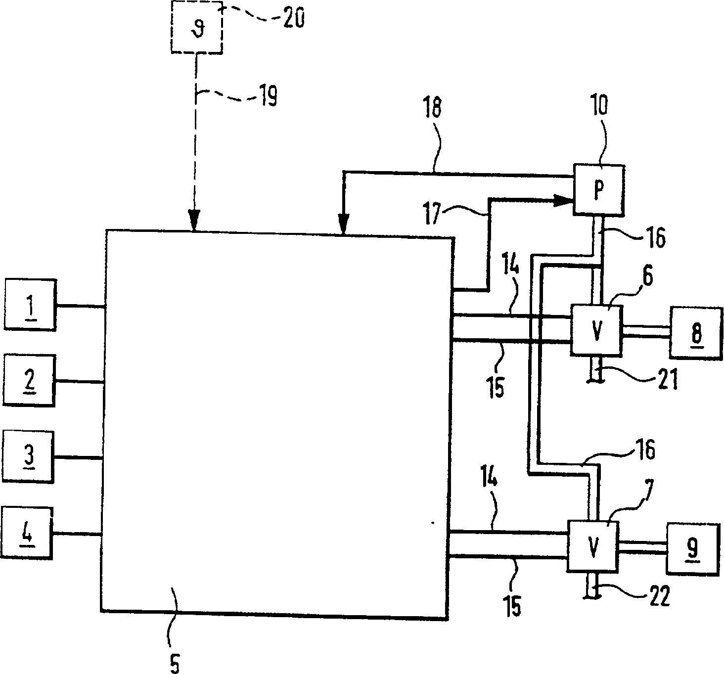
[0015] figure 1 A block diagram of a control unit of a brake system is shown, which performs drive slip control, antilock control, driving dynamics control and / or brake control of the driver of the vehicle by means of a pressure change at at least one wheel brake. Furthermore, speed sensors 1 - 4 are described which are connected to the wheels of the vehicle and which are connected to the electronic control unit 5 via corresponding signal lines. Also described are two wheel brakes 8 and 9 which are mounted on the driven wheels of the vehicle when the drive slip control is preferentially used. For the sake of brevity and clarity, the figure 1 Wheel brakes for other wheels are not described in . Electrically controlled valve arrangements 6 and 7 are mounted on the wheel brakes 8 and 9 by means of which the pressure on the wheel brakes can be controlled. Furthermore, each valve arrangement is connected via control lines 14 and 15 to an electrical control unit, whereby the valv...


PUM


Abstract

A process and device is proposed for controlling the braking system of a vehicle in which pressure is generated and released in the wheel brakes by pulses with at least one variable parameter. Here, the at least one parameter is corrected dependently upon at least one value which affects the pressure variation dynamics.

Description

technical field [0001] The invention relates to a control method and device for an automobile braking device. Background technique [0002] Such a method, or such a device, is known, for example, from DE-A 41 23 783 (US patent 5 419 622). It describes a drive slip control system in which, when a tendency to turn occurs on at least one drive wheel, the wheel with a tendency to turn is braked by controlling prearranged wheel brakes. The braking device described in this patent is a hydraulic braking device in which a pressure generating device (pump) is activated to control a valve arrangement to build or remove pressure on the wheel brake. In a known manner, starting from the deviation of the wheel speed of the turning-prone wheel from the reference speed, the pulse sequence of the pressure build-up or release is determined with pulses of predetermined length in order to build up or release the pressure in the range of drive slip control. [0003] Furthermore, it has not bee...

Claims


Application Information

Patent Timeline
Patent Type & Authority Patents(China)
IPC IPC(8): B60T8/34B60T8/175B60T8/1761B60T8/36B60T13/66
CPCB60T8/175B60T8/17616B60T8/36B60T13/66
Inventor 约翰内斯·施米特
Owner ROBERT BOSCH GMBH
Why Eureka
Try Eureka