
Air conditioner auxiliary heat exchange unit, air conditioner system, control method and environment simulation equipment

A technology for auxiliary heat exchange and air conditioning systems, applied in air conditioning systems, lighting and heating equipment, space heating and ventilation, etc. Efficiency, drag reduction effect

Pending Publication Date: 2020-07-28
北京创意信通科技有限责任公司
View PDF0 Cites 0 Cited by
  • Summary
  • Abstract
  • Description
  • Claims
  • Application Information

AI Technical Summary

Problems solved by technology

When cooling, the greater the difference between the set temperature and the actual temperature, the lower the temperature on the surface of the heat exchanger. At this time, if the temperature on the surface of the heat exchanger is lower than the dew point temperature of the air, condensation will occur on the surface of the heat exchanger water, thereby reducing the humidity of the air. This decrease in air humidity is not within control, resulting in a continuous decrease in air humidity, which has an adverse effect on humidity control. If the environment requires high humidity, a humidifier is required to increase the humidity, resulting in waste of resources
Although increasing the wind speed can improve this problem, the increase in wind speed is limited, and the side effects are loud noise, even structural vibration, and a large increase in power consumption

Method used


Image

  • Air conditioner auxiliary heat exchange unit, air conditioner system, control method and environment simulation equipment
  • Air conditioner auxiliary heat exchange unit, air conditioner system, control method and environment simulation equipment
  • Air conditioner auxiliary heat exchange unit, air conditioner system, control method and environment simulation equipment

Examples


Embodiment Construction

[0075] Reference will now be made in detail to the exemplary embodiments, examples of which are illustrated in the accompanying drawings. When the following description refers to the accompanying drawings, the same numerals in different drawings refer to the same or similar elements unless otherwise indicated. The implementations described in the following exemplary examples do not represent all implementations consistent with the present invention. Rather, they are merely examples of apparatuses and methods consistent with aspects of the invention as recited in the appended claims.

[0076] The terminology used in the present invention is for the purpose of describing particular embodiments only and is not intended to limit the invention. As used herein and in the appended claims, the singular forms "a", "the", and "the" are intended to include the plural forms as well, unless the context clearly dictates otherwise. It should also be understood that the term "and / or" as use...


PUM


Abstract

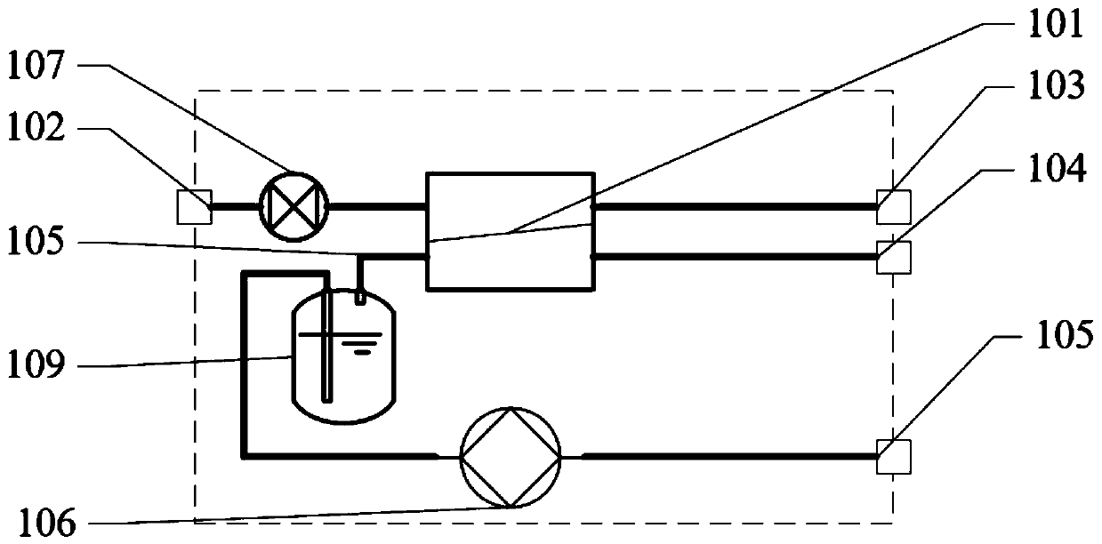
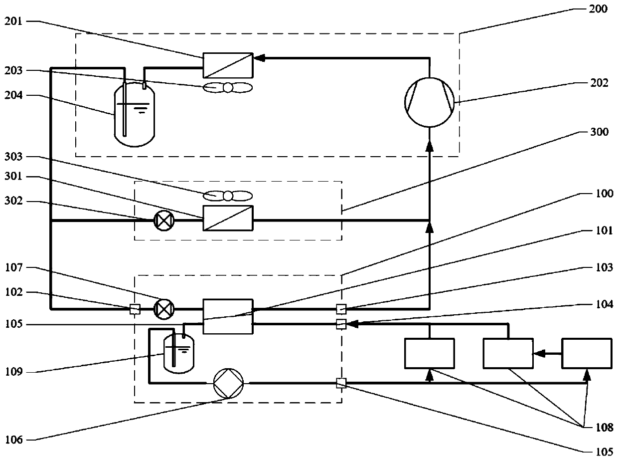
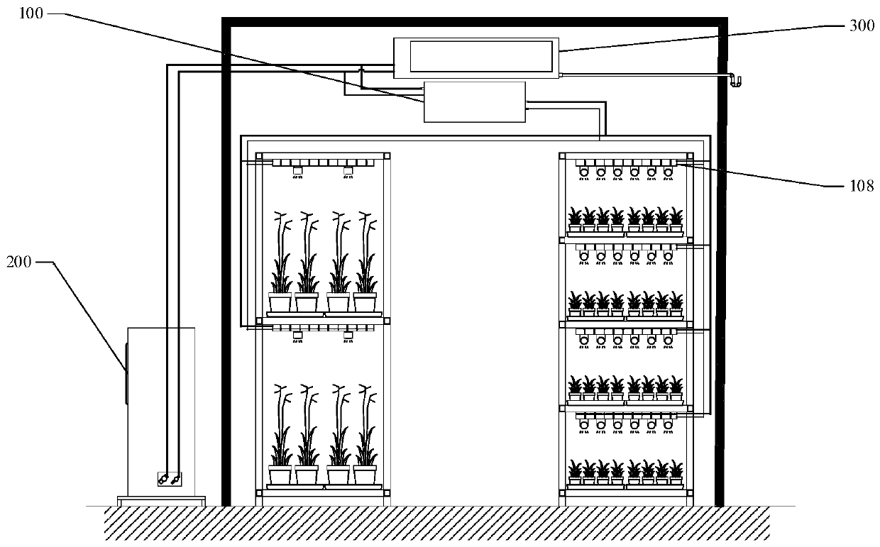
The invention relates to the technical field of artificial environment control and air conditioners, in particular to an air conditioner auxiliary heat exchange unit, an air conditioner system, a control method and environment simulation equipment. The air conditioner auxiliary heat exchange unit comprises a heat exchanger, an air conditioner inlet pipeline and an air conditioner outlet pipeline,wherein one end of the air conditioner inlet pipeline communicates with one end of the air conditioner outlet pipeline through the heat exchanger; a heat exchange inlet pipeline and a heat exchange outlet pipeline are further arranged on the heat exchanger; the heat exchange inlet pipeline communicates with the heat exchange outlet pipeline through the heat exchanger; and a pump is arranged on theheat exchange inlet pipeline or the heat exchange outlet pipeline. On the other hand, the air conditioner system comprising the air conditioner auxiliary heat exchange unit, the control method and the environment simulation equipment are further provided. A foundation is provided for an air conditioner to be connected into other radiators through the air conditioner auxiliary heat exchange unit,so that heat conduction and heat radiation are used for assisting the air conditioner system in regulating and controlling the closed-space temperature, and low-wind-speed and high-efficiency temperature regulation and control are met.

Description

technical field [0001] The invention relates to the field of artificial environment control technology and air-conditioning technology, in particular to an air-conditioning auxiliary heat exchange unit, an air-conditioning system, a control method, and an environment simulation device. Background technique [0002] The traditional air-conditioning system mainly includes a condenser, a compressor, an evaporator, and an expansion valve. The compressor solves the problem of heat energy transfer in the room (enclosed space) against the temperature of the external environment, so that the room can be cooled in high temperature weather, and the room can be cooled in low temperature weather. It can be heated, so it has been widely used in the temperature control of closed environments. [0003] Because the traditional air conditioner uses a heat exchanger to regulate the air temperature indoors, supplemented by a fan, the air can flow quickly to achieve uniform temperature, thereby...

Claims


Application Information

Patent Timeline
IPC IPC(8): F24F5/00F24F1/0003F24F11/84F24F13/22F24F13/30F25B1/00F25B41/06F25B41/31
CPCF24F5/001F24F1/0003F24F13/30F24F11/84F24F13/22F25B1/00F24F2013/221F25B41/31
Inventor 钱晓峰
Owner 北京创意信通科技有限责任公司
Learn More