A communication line erector
A technology of communication lines and erectors, applied in the field of communication, can solve the problem that different communication lines cannot be erected at different heights
- Summary
- Abstract
- Description
- Claims
- Application Information
AI Technical Summary
Problems solved by technology
Method used
Image
Examples
specific Embodiment approach 1
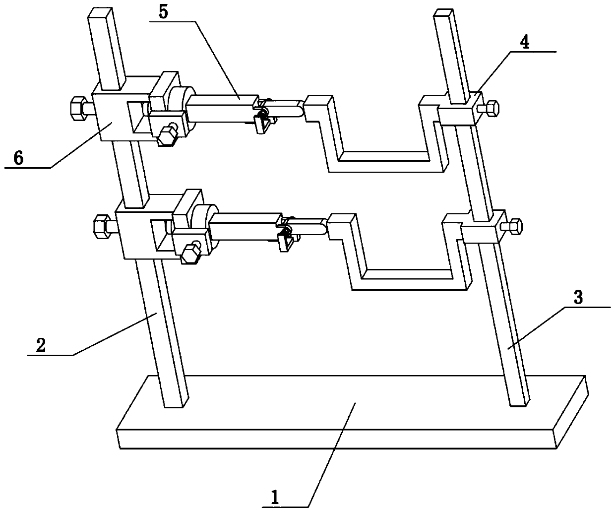
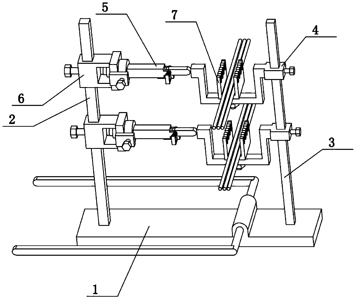
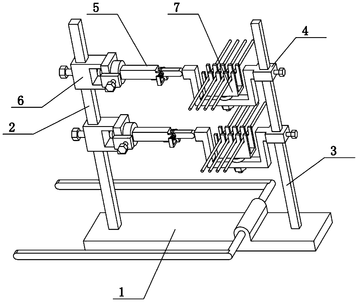
[0043] Combine below Figure 1-16 Describe this embodiment, the present invention relates to the field of communication, more specifically a communication line erector, including a base plate 1, a left column 2, a right column 3, a wire frame 4, a horizontal column 5, a rotating rod 503 and a slider 6. The present invention is provided with multiple layers, so that different communication lines can be erected at different heights, and the lines can be easily moved between multiple layers during erection.
[0044]The left and right ends of the base plate 1 are respectively fixedly connected with a left column 2 and a right column 3, a plurality of wire racks 4 are arranged on the right column 3, a plurality of sliders 6 are arranged on the left column 2, and a plurality of sliders 6 The right ends of each are fixedly connected with cross-columns 5, and the plurality of cross-columns 5 are respectively corresponding to the plurality of wire racks 4, and the right ends of the plu...
specific Embodiment approach 2
[0046] Combine below Figure 1-16 To illustrate this embodiment, the right ends of the plurality of wire racks 4 are all slidably connected to the right upright post 3, and the right ends of the plurality of wire racks 4 are all threadedly connected with fastening screws 1, and the plurality of fastening screws 1 are all supported on the right side. On the upright post 3, thereby a plurality of wire racks 4 are fixed on the right upright post 3, and a plurality of sliders 6 are all slidably connected on the left upright post 2, and a plurality of sliders 6 are all threadedly connected with fastening screws II, and a plurality of The fastening screws II are all supported on the left column 2, thereby fixing a plurality of slide blocks 6 on the left column 2. A plurality of wire racks 4 can slide vertically on the right column 3, and fastening screw 1 is used to fix the wire rack 4 on the right column 3; a plurality of slide blocks 6 can vertically slide on the left column 2, ti...
specific Embodiment approach 3
[0048] Combine below Figure 1-16 To illustrate this embodiment, the plurality of wire racks 4 are all provided with a wire rack 401 . When the communication line rack is placed on the wire rack 4, the communication line should be placed on the wire rack 401 to prevent the communication line from sliding from the wire rack 4 left and right.
PUM
 Abstract
Description
Claims
Application Information
 - R&D
- Intellectual Property
- Life Sciences
- Materials
- Tech Scout
- Unparalleled Data Quality
- Higher Quality Content
- 60% Fewer Hallucinations
Browse by: Latest US Patents, China's latest patents, Technical Efficacy Thesaurus, Application Domain, Technology Topic, Popular Technical Reports.
© 2025 PatSnap. All rights reserved.Legal|Privacy policy|Modern Slavery Act Transparency Statement|Sitemap|About US| Contact US: help@patsnap.com


