
Hardware debugging method of digital microphone

A technology for digital microphone and hardware debugging, applied in the direction of microphone port/microphone accessories, etc., can solve the problems of wrong pin connection of digital microphone, encapsulation of digital microphone, inability to recognize voice recognition effect, and difficulty in checking the recording sequence of microphones. Guarantee product performance, avoid repeated debugging, save time and cost

Active Publication Date: 2019-07-30
AMOLOGIC (SHANGHAI) CO LTD
View PDF8 Cites 8 Cited by
  • Summary
  • Abstract
  • Description
  • Claims
  • Application Information

AI Technical Summary

Problems solved by technology

However, in the application process, one data interface of the digital microphone is connected to two microphones. When a microphone is soldered incorrectly, it is difficult to check from the test waveform and test data, and it is also difficult to check the recording sequence of the microphones. Different digital microphones There are differences in the definition of the pins of the manufacturers, which often lead to wrong connection of the pins of the digital microphone and wrong packaging. The above reasons often lead to unrecognizable voice or poor voice recognition effect.
According to the actual use, it is found that the voice cannot be recognized or the voice recognition effect is poor, and then the reason is found. The above methods need to waste a lot of time, manpower and money, and cannot completely solve the problem of the virtual soldering of the microphone. Whether the order of the microphone pickup holes is correct and whether the electrical performance meets the requirements And a series of problems, especially for the case of a microphone with weak soldering, the industry has not found a good way to eliminate it

Method used


Image

  • Hardware debugging method of digital microphone
  • Hardware debugging method of digital microphone
  • Hardware debugging method of digital microphone

Examples


Embodiment Construction

[0035] The technical solutions in the embodiments of the present invention will be clearly and completely described below in conjunction with the accompanying drawings in the embodiments of the present invention. Obviously, the described embodiments are only some of the embodiments of the present invention, not all of them. Based on the embodiments of the present invention, all other embodiments obtained by persons of ordinary skill in the art without creative work all belong to the protection scope of the present invention.

[0036] It should be noted that, in the case of no conflict, the embodiments of the present invention and the features in the embodiments can be combined with each other.

[0037] The present invention will be further described below in conjunction with accompanying drawing and specific embodiment, but not as limitation of the present invention.

[0038] The present invention includes a hardware debugging method of a digital microphone, where the digital ...


PUM


Abstract

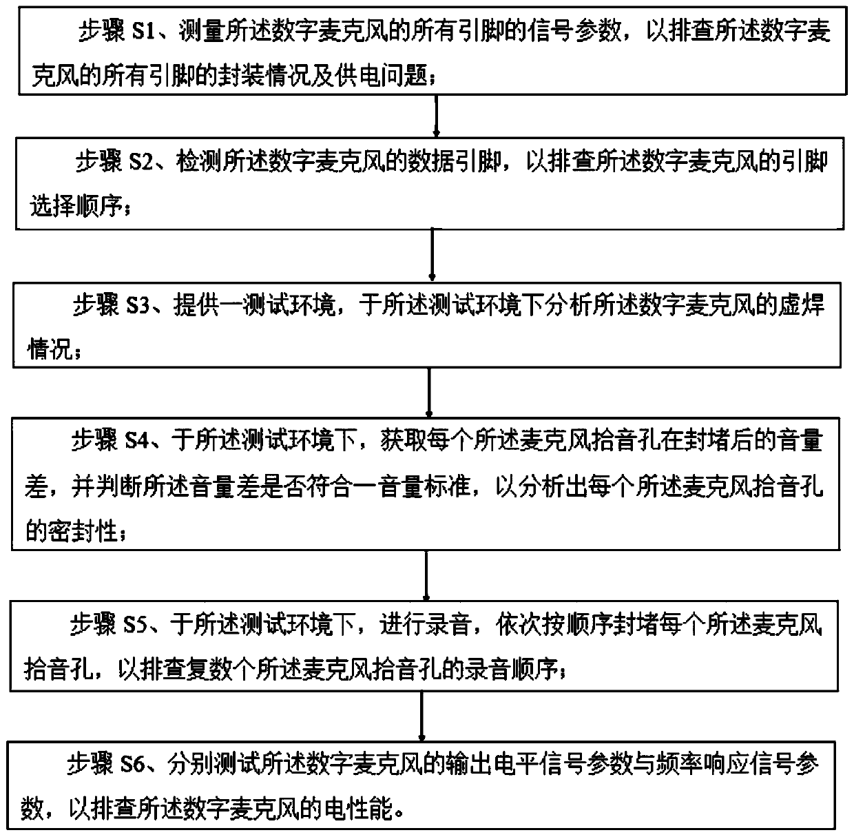
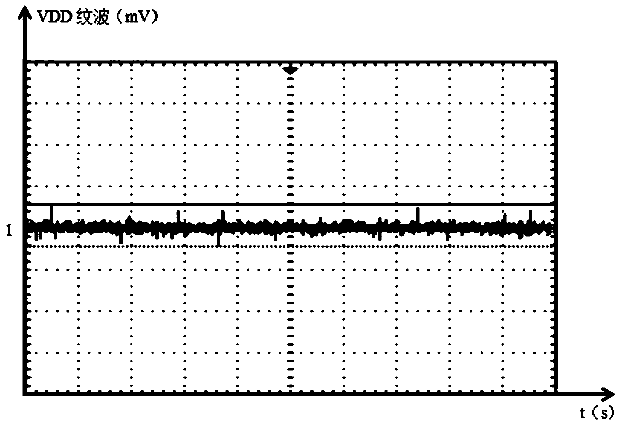
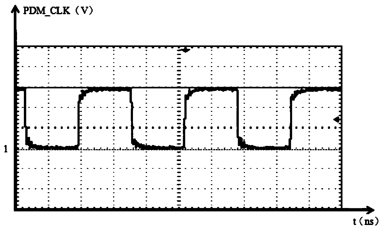
The invention discloses a hardware debugging method of a digital microphone, wherein the method comprises the steps of S1, measuring the signal parameters of all pins of the digital microphone; s2, detecting a data pin of the digital microphone so as to check a pin selection sequence of the digital microphone; step S3, analyzing the pseudo soldering condition of the digital microphone in a test environment; s4, acquiring the volume difference of each microphone pickup hole after plugging, and judging whether the volume difference meets a volume standard or not, so as to analyze the sealing performance of each microphone pickup hole; step S5, recording in a test environment, and blocking each microphone pickup hole sequentially according to a sequence so as to check the recording sequence of the plurality of microphone pickup holes; and S6, respectively testing the output level signal parameter and the frequency response signal parameter of the digital microphone so as to check the electrical performance of the digital microphone. The method has the beneficial effects of being simple to operate, avoiding the repeated debugging, saving the time and cost and avoiding the resource waste.

Description

technical field [0001] The invention relates to the technical field of digital microphones, in particular to a hardware debugging method of a digital microphone. Background technique [0002] With the popularization and application of smart electronic products, smart TVs, smart set-top boxes, smart speakers, etc. are electronic products that require voice control, and their voice control needs to be processed by a microphone. The voice recognition function of the microphone is very important for voice-controlled electronic products. . Microphones include analog microphones and digital microphones. Digital microphones transfer the analog-to-digital conversion function from the encoder to the microphone, enabling an all-digital audio capture channel from the microphone to the processor. [0003] In the prior art, due to the strong anti-interference ability of the digital microphone and the consistent and stable electrical performance, many electronic products related to voice...

Claims


Application Information

Patent Timeline
IPC IPC(8): H04R1/08
CPCH04R1/08
Inventor 张坤
Owner AMOLOGIC (SHANGHAI) CO LTD
Learn More