MEMS laser scanner having enlarged fov

A scanner, polarized light technology, applied in the field of MEMS laser scanners with magnified FOV, can solve problems such as hindering the pivoting movement range of MEMS mirrors

Pending Publication Date: 2019-07-30
MICROSOFT TECH LICENSING LLC
View PDF11 Cites 2 Cited by
  • Summary
  • Abstract
  • Description
  • Claims
  • Application Information

AI Technical Summary

Problems solved by technology

However, various factors impede the range of pivotal motion of the MEMS mirror during the scan of the image frame

Method used


Image

  • MEMS laser scanner having enlarged fov
  • MEMS laser scanner having enlarged fov
  • MEMS laser scanner having enlarged fov

Examples


Embodiment Construction

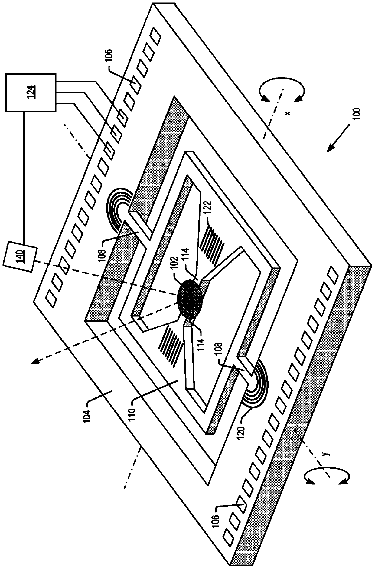
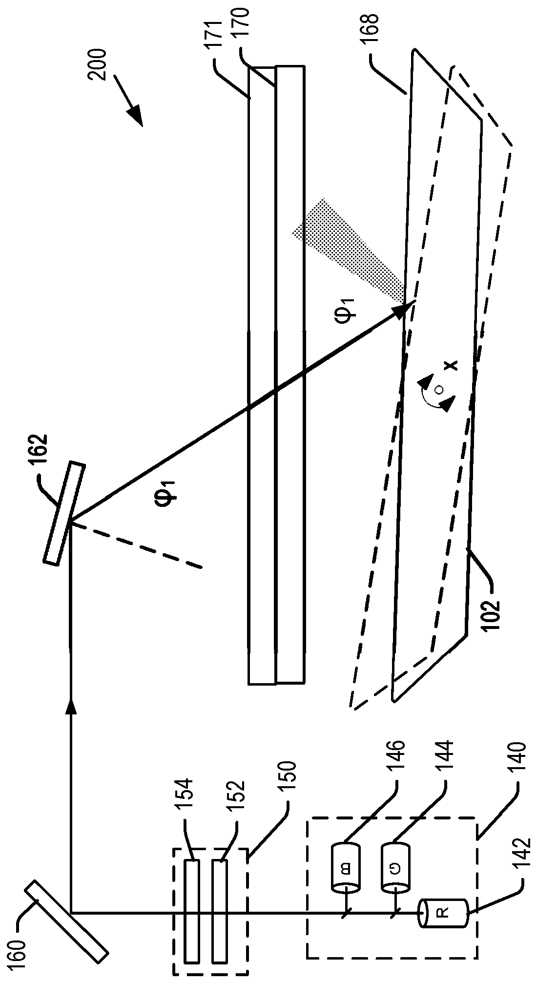
[0028] Certain embodiments of the present technology can be used to increase (also referred to as extend) the FOV that can be supported by, for example, MEMS laser scanners used in near-eye displays. In an embodiment, a MEMS laser scanner includes a display engine including, for example, a plurality of laser diodes emitting light at red, green, and blue (RGB) wavelengths. Light from the display engine is directed onto the optics of the beam scanning assembly. In one embodiment, the optical element may be a mirror.

[0029] The optical element is supported by the bend to pivot about two axes, referred to herein as the x and y axes, which in embodiments may be coplanar and orthogonal to each other. The beam scanning assembly also includes a dual axis drive to pivot the optical element about the axis. The dual-axis drivers and laser diodes can be coupled to a controller that coordinates the emission of the respective RGB lasers with the x,y positioning of the optics through the...


PUM


Abstract

A MEMS laser scanner is disclosed for use in a near-eye display including an increased field of view (FOV). One or more Brag polarization gratings are disposed on the scanning element such that lightof one polarization is directed in one direction to form a first portion of the FOV, with light of a second polarization directed in a second, different direction to form a second, different portion of the FOV. Using light of different polarizations, the MEMS laser scanner is able to expand the FOV without increasing the range over which the mirror of the scanner oscillates.

Description

Background technique [0001] Various types of computing, entertainment, and / or mobile devices can be implemented with near-eye transparent or translucent displays. The near-eye display may include a transparent or translucent display through which the user can view the surrounding environment and also see virtual objects generated on the display to make it appear to be part of and / or overlaid on the surrounding environment. An image of an object (eg, text, graphics, video, etc.). [0002] Near-eye displays are typically implemented using spatial light modulation (SLM) systems including, for example, liquid crystal on silicon (LCoS) display engines and digital light processing (DLP) display engines for image generation. LCoS and DLP display systems simultaneously project all pixels in an image to modulate the amplitude, phase, intensity or polarization of light on the image. Another emerging technology is microelectromechanical (MEMS) laser scanners. MEMS laser scanners typic...

Claims


Application Information

Patent Timeline
IPC IPC(8): G02B5/30G02B26/08
CPCG02B5/1833G02B5/3016G02B26/0808G02B26/0833G02B26/101G02B27/0172G02B27/1086G02B27/283G02B27/4227G02B27/4261
Inventor S·J·罗宾斯E·格利克何斯慧楼歆晔
Owner MICROSOFT TECH LICENSING LLC
Why Eureka
Try Eureka