Near eye display prism optic assembly

a technology of optic assembly and display lens, which is applied in the field of near eye, head or helmetmounted display system, weapon sight viewer, handheld viewing device, can solve the problems of reducing the usable eye relief of such a device, known sources will have several performance flaws, etc., and achieve the effect of magnifying the image of a micro-display and comfortably presenting immersive imagery

Inactive Publication Date: 2012-02-28
UNITED STATES OF AMERICA THE AS REPRESENTED BY THE SEC OF THE ARMY
View PDF19 Cites 52 Cited by
  • Summary
  • Abstract
  • Description
  • Claims
  • Application Information

AI Technical Summary

Benefits of technology

[0007]Exemplary embodiments are disclosed to allow imaging large display format sizes as needed. Such exemplary embodiments can have continuous surface profiles throughout optically active areas on prism optic, which allow large pupil sizes and the ability to be scaled to different sizes and formats.
[0015]In one exemplary embodiment, lightweight, plastic prism Optic is used with an aspheric surface in conjunction with a glass corrector optic to magnify the image of a micro-display and very comfortably present the immersive imagery to a user.

Problems solved by technology

While such known display image sources can scale to diagonal dimension of less than or equal to 15 mm, these known sources will have several performance flaws if scaled to image sources with a diagonal dimension of greater than 15 mm.
This is due to the limited optical path associated with such known prism arrangements.
All optical plastic elements require glass sacrificial windows to protect the delicate plastic material during normal use, decreasing the usable eye relief of such a device.

Method used


Image

  • Near eye display prism optic assembly
  • Near eye display prism optic assembly
  • Near eye display prism optic assembly

Examples


Embodiment Construction

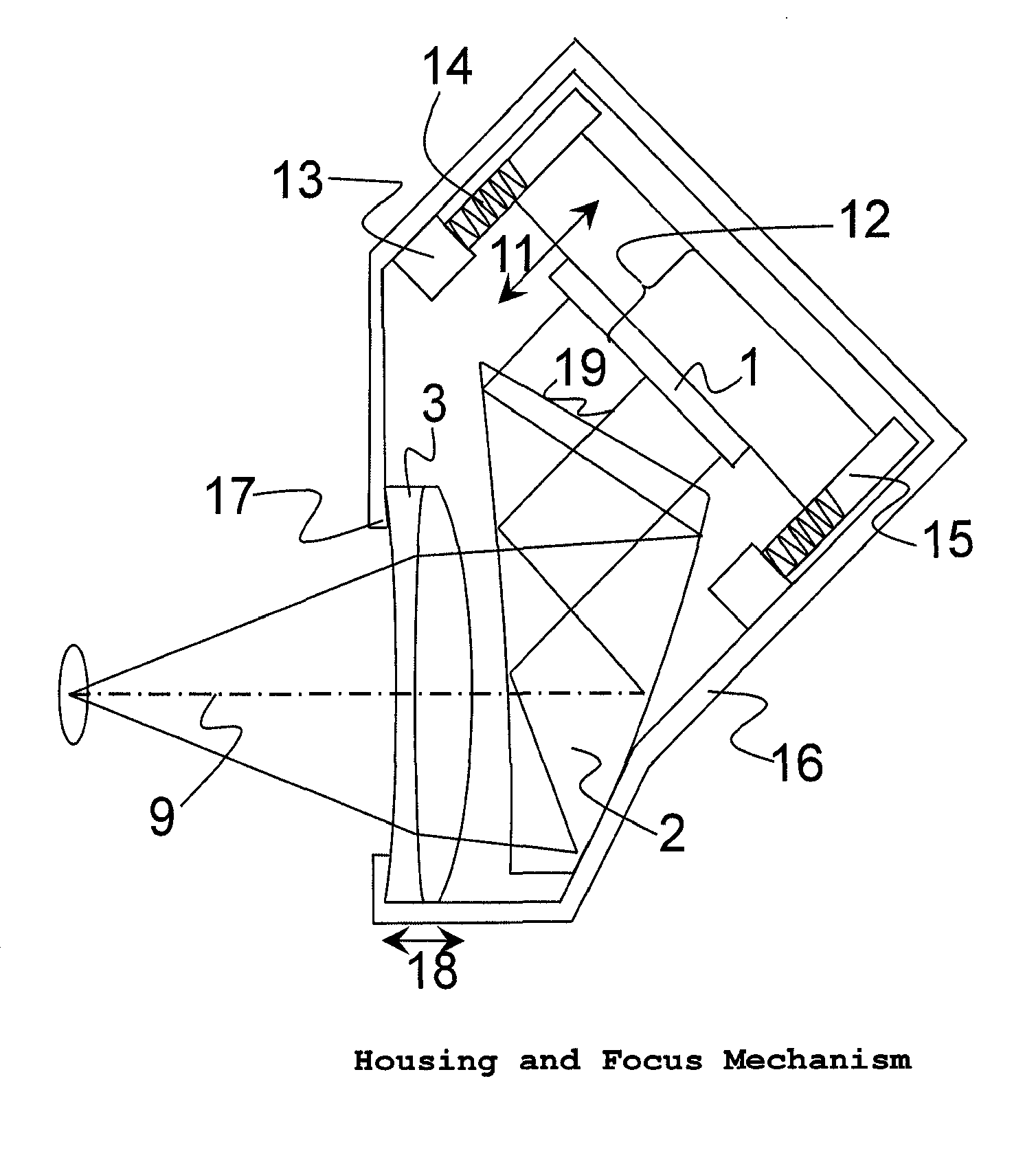
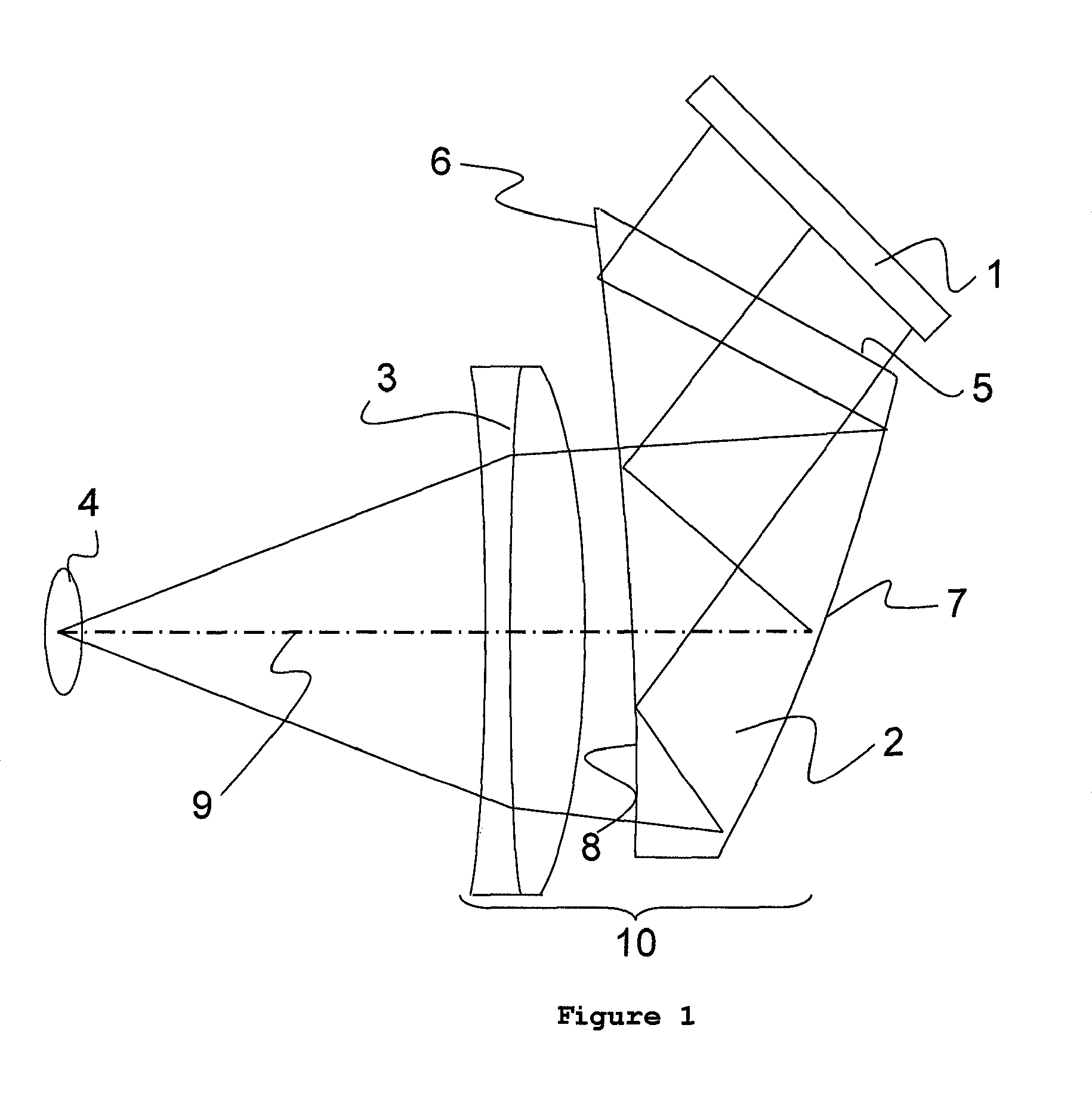
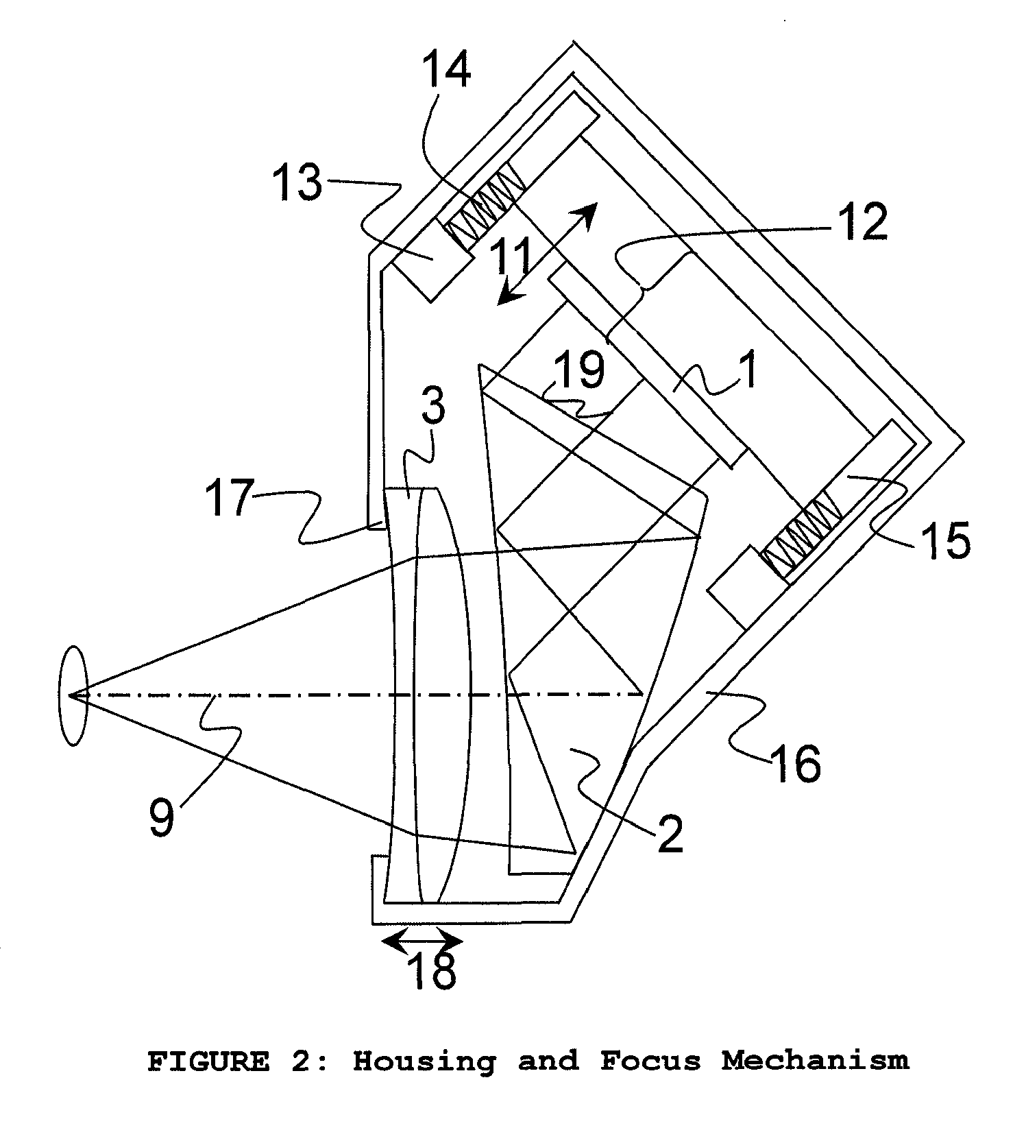
[0025]A detailed description is provided in reference to an exemplary embodiment shown in FIG. 1.

[0026]FIG. 1 illustrates an optical schematic of an exemplary embodiment of Prism Optic Assembly (POA). This figure shows an exemplary layout of the integrated optical components and depicts a representation of the optical path from a micro-display 1 to the eye 4 in a horizontal view of a vertical cross-section as shown.

[0027]The POA 10 comprises an optical member 2 and a corrector lens grouping 3. The optical member 2 has three adjacent optical surfaces, two of which are curved surfaces; the other surface is flat. The volume between these surfaces together with their mutually orthogonal edge faces is filled with an optical polymer. Such a prism optic is ideally comprised of an optical plastic that can be diamond turned or molded to create the 3 optical surfaces and mechanical mounting features. However, this prism can also be molded or ground in glass or some other optical material that...


PUM


Abstract

An optical assembly uses a plastic prism with one flat surface and a collimating lens optic to provide the capability of imaging a color micro-display to the eye. The collimating optic and flat prism surface can allow for aberration-free diopter adjustment and an image with very low-magnitude, nearly-symmetric distortion. The collimating optic can also provide environmental protection of the prism involving an optical plastic device. The input illumination from the micro-display enters the prism, is reflected two times within the prism, exits the prism, and passes through the collimating optic before being viewed by the eye. Such an optical assembly can provide a field of view with eye-relief and exit pupil when viewing a full-color micro-display.

Description

GOVERNMENT INTEREST[0001]The invention described herein may be manufactured, used, sold, imported and / or licensed by or for the United States Government.FIELD OF THE DISCLOSURE[0002]The disclosure relates to near eye, head or helmet-mounted display systems, weapon sight viewers, and handheld viewing devices, incorporating micro-display technologies.BACKGROUND INFORMATION[0003]Most prior art in the area of monolithic prisms for micro-display imaging have similar properties. Such patents describe a prism with three optically-active surfaces, which can be used with and without a corrector optic.[0004]Recent developments in micro-display technology have created large-format, full-color micro-displays. A new near-eye optical imaging approach is needed to fully realize the size and resolution of these displays with wide fields of view and large eye pupils. Also to use such a device effectively in a system concept, the imaging device must allow a large range of diopter adjustment for comfo...

Claims


Application Information

Patent Timeline
Patent Type & Authority Patents(United States)
IPC IPC(8): G02B27/14G02B3/04
CPCG02B5/04G02B13/10G02B13/22G02B27/0172G02B27/30G02B2027/011G02B2027/0116G02B2027/0123Y10S359/90
Inventor BRYANT, KYLE R.REESE, COLIN E.HEIMER, RICHARD J.
Owner UNITED STATES OF AMERICA THE AS REPRESENTED BY THE SEC OF THE ARMY
Why Eureka
Try Eureka