Laser scanner

A laser scanner and laser beam technology, applied in the field of laser scanners, can solve the problem of small scanning range and achieve the effects of fast scanning speed, wide scanning range and high precision

Inactive Publication Date: 2013-04-17
LAIZE PHOTONICS CO LTD
View PDF4 Cites 9 Cited by
  • Summary
  • Abstract
  • Description
  • Claims
  • Application Information

AI Technical Summary

Problems solved by technology

But because it uses the diffracted light after the light beam passes through the acousto-optic deflector to scan

Method used


Image

  • Laser scanner

Examples


Embodiment Construction

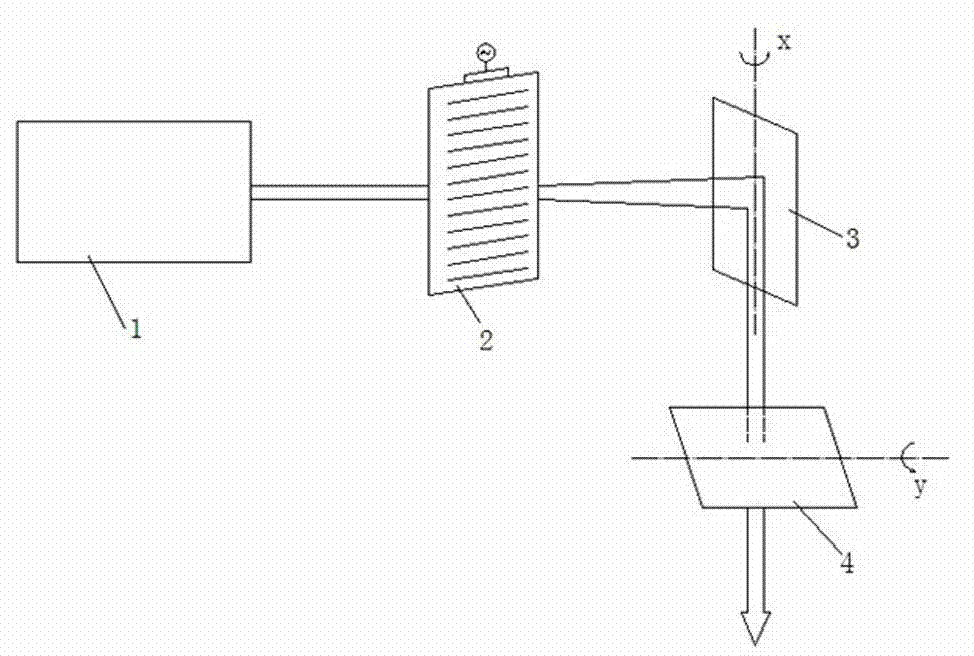
[0008] see figure 1 , a scanner of the present invention is characterized in that it includes: an acousto-optic deflector 2, which is used to diffract the laser beam emitted by the laser 1, and can quickly and accurately control the diffracted beam by controlling the input electrical signal; the vibrating mirror system (x-direction scanning galvanometer 3 and y-direction scanning galvanometer 4), which reflect the diffracted beam from the acousto-optic deflector 2 and realize large-format scanning through its large-angle twist.

[0009] The acousto-optic deflector 2 includes a piezoelectric transducer and an acousto-optic medium for transmitting ultrasonic waves (belongs to conventional technology?).

[0010] The vibrating mirror system includes: reflective mirrors, high-speed swing motors and their control circuits. The control circuit controls two sets of motors to drive the reflective mirrors of vibrating mirrors 3 and 4 to swing at high speed (a conventional technology). ...


PUM


Abstract

The invention discloses a laser scanner which comprises an acousto-optic deflection device and a mechanical galvanometer system. Light beams sent out by the laser diffract through the acousto-optic deflection device, and diffraction light beams can achieve rapid and accurate regulation by controlling input electrical signals; and then the diffraction light beams are reflected through the galvanometer system, and large-breadth scanning is achieved through wide-angle twisting of the galvanometer system. Therefore, the laser scanner can achieve high-speed high-precision and large-breadth optical scanning, and can be widely applied to aspects such as laser precision marking, laser rapid molding and laser radars.

Description

technical field [0001] The invention relates to a laser scanner, which can be widely used in laser precision marking, laser rapid prototyping, laser radar and the like. Background technique [0002] At present, as optical scanners used for drawing by optical scanning in laser marking and the like, there are mainly methods such as mechanical rotating mirror-galvanometer system scanning, galvanometer scanning, and resonant mirror scanning. Among them, the scanning device of the mechanical rotating mirror-galvanometer system is composed of a casing, a vibrating mirror, and a coil that generates an alternating voltage in order to vibrate the vibrating mirror. When an alternating current is passed through the coil to generate an alternating magnetic field, the vibrating mirror vibrates in resonance to perform optical scanning. Since the oscillating angle of the vibrating mirror can be very large, the advantage of this scanning device is that the scanning range is large, but this...

Claims


Application Information

Patent Timeline
IPC IPC(8): G02F1/11G02B26/10
Inventor 郭林
Owner LAIZE PHOTONICS CO LTD
Why Eureka
Try Eureka