Shaft centrifugal type clamp

A centrifugal, fixture technology, applied in the mechanical field, can solve the problem of time-consuming clamping of workpieces, and achieve the effect of saving time

Active Publication Date: 2019-08-02
NINGDE NORMAL UNIV +1
View PDF7 Cites 4 Cited by
  • Summary
  • Abstract
  • Description
  • Claims
  • Application Information

AI Technical Summary

Problems solved by technology

[0003] For this reason, it is necessary to provide a shaft type centrifugal fixture to solve the time-consuming problem of clamping workpieces on existing lathes

Method used


Image

  • Shaft centrifugal type clamp
  • Shaft centrifugal type clamp
  • Shaft centrifugal type clamp

Examples


Embodiment Construction

[0030] In order to explain in detail the technical content, structural features, achieved goals and effects of the technical solution, the following will be described in detail in conjunction with specific embodiments and accompanying drawings.

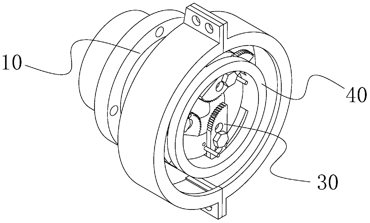
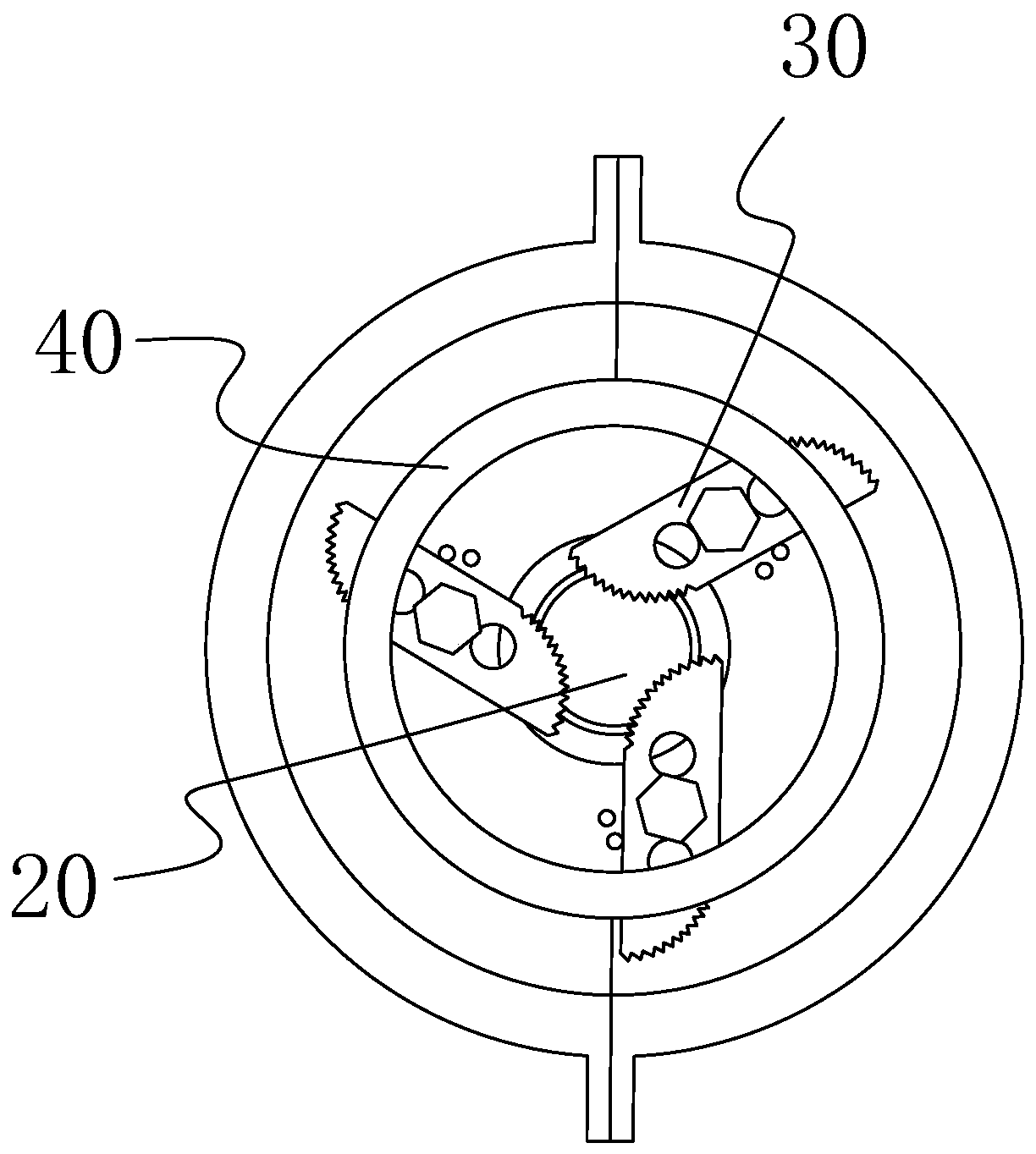
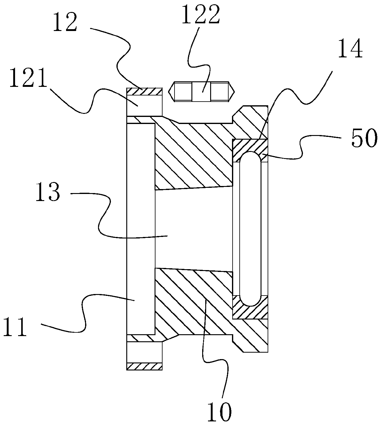
[0031] see Figure 1 to Figure 6 , The present embodiment provides a shaft type centrifugal clamp, including a faceplate 10 , a rotating center 20 , a jaw mechanism 30 , a sliding seat 40 and an annular fixing seat 50 . The faceplate is a hollow structure as a whole, with shoulders at both ends. A connection groove 11 is provided at one end of the faceplate. The connection groove is used for socketing with the spindle of the lathe, and a threaded hole 121 is punched on the shoulder 12 at one end of the connection groove. A plurality of threaded holes are arranged in a circle on the shaft shoulder with one end of the connecting groove, and then the faceplate is locked on the lathe spindle with fixing bolts 122. In this embodiment, the ...


PUM


Abstract

The invention discloses a shaft centrifugal type clamp. The clamp comprises a faceplate, a rotating center, a claw mechanism, a sliding seat and an annular fixing seat, wherein the faceplate is fixedon a lathe spindle, so that the faceplate can rotate along with the lathe spindle, the annular fixing seat is arranged on a fixing groove of the faceplate, and the sliding seat is connected in the annular fixing seat in a sleeved mode. Firstly, a workpiece passes through the centers between the rotating center and the center on the lathe tailstock, when the faceplate rotates, the annular fixing seat can be driven to rotate, the sliding seat can rotate relative to the annular fixing seat, meanwhile, the clamping jaw mechanism installed on the sliding seat is subjected to centrifugal rotation, so that the plurality of clamping jaws can fasten the workpiece under the action of centrifugal force, the purpose of clamping and fixing the workpiece is achieved, when the lathe spindle stops rotating, an extruded reset spring can stretch the sliding seat in the reverse direction of an annular reset groove, so that the plurality of claws rotate reversely to remove the workpiece, so that people can conveniently take down the workpiece, and the time for clamping the workpiece is saved.

Description

technical field [0001] The invention relates to the mechanical field, in particular to a shaft type centrifugal clamp. Background technique [0002] When the lathe is processing shaft parts, it takes a lot of auxiliary time to clamp the parts, which increases the labor time of the workers. For manual clamping parts, it is easy to cause manual errors, that is, the coaxiality of the outer circle of the workpiece and the center hole. Cause deviation and affect the accuracy of the workpiece. Contents of the invention [0003] Therefore, it is necessary to provide a shaft-type centrifugal fixture to solve the time-consuming problem of clamping workpieces in existing lathes. [0004] In order to achieve the above object, the inventor provides a shaft type centrifugal clamp, which includes a faceplate, a rotating top, a claw mechanism, a sliding seat and an annular fixed seat; one end of the faceplate is provided with a connecting groove, and the other end of the faceplate Ther...

Claims


Application Information

Patent Timeline
Patent Type & Authority Applications(China)
IPC IPC(8): B23B31/14
CPCB23B31/14
Inventor 缪海滔陈盛其余亚飞夏颖凤
Owner NINGDE NORMAL UNIV
Why Eureka
Try Eureka