A CNC machine tool machining center fixture

A technology of machining centers and CNC machine tools, applied in the direction of manufacturing tools, metal processing equipment, metal processing machinery parts, etc., can solve problems such as unfavorable production and development of enterprises, affecting processing accuracy, complicated clamping steps, etc., to achieve easy disassembly and assembly operations. , The effect of high clamping stability and reducing the scrap rate of workpieces

Active Publication Date: 2020-11-17
YANGZHOU SUPER MASCH TOOL CO LTD
View PDF8 Cites 0 Cited by
  • Summary
  • Abstract
  • Description
  • Claims
  • Application Information

AI Technical Summary

Problems solved by technology

[0002] CNC machine tool is a high-precision and high-efficiency automatic machine tool, equipped with multi-station turret or power turret, has a wide range of processing performance, and can process linear cylinders, oblique cylinders, arcs and various threads, grooves, Complex workpieces such as worms have various compensation functions such as linear interpolation and circular interpolation, and have played a good economic effect in the mass production of complex parts. For processing, the existing fixtures used for CNC machine tools have complicated clamping steps, are not easy to quickly disassemble and assemble, greatly affect the processing efficiency, and the clamping effect is poor, affecting the machining accuracy, which can easily lead to the scrapping of the workpiece, which is not conducive to the production and development of the enterprise.

Method used


Image

  • A CNC machine tool machining center fixture
  • A CNC machine tool machining center fixture
  • A CNC machine tool machining center fixture

Examples


Embodiment 1

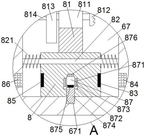
[0028] When the workpiece needs to be clamped, the third electromagnetic coil device 876 is powered on, so that the third electromagnetic coil device 876 and the third magnetic block 875 generate an attractive force, and then the lock slider 874 drives the limit block 872 to overcome the top of the fourth spring 873. The pressure slides upward until the lock slider 874 completely slides out of the lock groove 671. At the same time, the first electromagnetic coil device 86 is controlled to be powered on, so that the first electromagnetic coil device 86 and the first magnetic block 85 generate an attractive force, and then the mobile slide The table 8 slides to the leftmost position in the second inner cavity 67 to the greatest extent against the pressing force of the third spring 821 on the left side. At this time, the second spline shaft 814 is power-fitted with the second inner spline rotary sleeve 666. , at the same time, make the fourth gear 813 and the second gear 682 in a ...

Embodiment 2

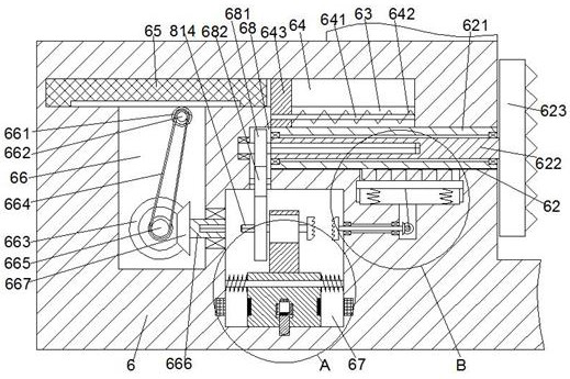
[0030] When the workpiece needs to be rotated and processed, the mobile slide table 8 is kept in the initial state, and at the same time, the lock slider 874 and the lock groove 671 are in a locked connection state and the fourth gear 813 is in a meshed connection state with the second gear 682, Then, the rotation of the fourth gear 813 is controlled by the drive motor 811, and then the fourth gear 813 drives the second gear 682 and the first gear 681 to rotate. At this time, the first gear 681 drives the first spline shaft 624 and the first inner When the splined rotating sleeve 622 rotates, the first inner splined rotating sleeve 622 drives the second clamping disc 623 to rotate, and then the workpiece between the second clamping disc 623 and the first clamping disc 611 is driven to rotate.

Embodiment 3

[0032] When the workpiece needs to be taken out, the second electromagnetic coil device 84 is controlled to be powered on, so that the second electromagnetic coil device 84 and the second magnetic block 83 generate an attractive force, and then the movable slide table 8 overcomes the pressing force of the third spring 821 on the right side to the maximum extent. Slide to the rightmost position in the second inner cavity 67. At this time, the second connecting toothed plate 812 on the right side of the support platform 81 is connected with the first connecting toothed plate 6962 in power fit, and at the same time, the left side of the supporting platform 81 The fourth gear 813 is disengaged from the second gear 682, and then drives the second connecting toothed plate 812 to rotate through the driving motor 811, and then the second connecting toothed plate 812 drives the first connecting toothed plate 6962, the rotating shaft 696 and the fourth cone. The gear 6961 rotates. At thi...


PUM


Abstract

The invention discloses a clamp of a numerical control machine tool machining center. The clamp of the numerical control machine tool machining center comprises a clamp rack, wherein a front-and-backthrough-arranged machining area is arranged in a top end surface of the clamp rack, a first clamping disc is rotationally matched with a right side wall of the machining area in a rotating mode, a first sliding cavity which extends leftwards and rightwards is arranged in a left side wall of the machining area, the tail end of the right side of the first sliding cavity communicates with the machining area, the first sliding cavity is in sliding fit connection with a first sliding block, a first inner cavity communicates with the tail end of the left side of the first sliding cavity, a second inner cavity communicates with the bottom of the first inner cavity, a second sliding cavity which extends towards the left side is formed in the upper side of the first sliding cavity, and a through sliding groove is formed between the second sliding cavity and the first sliding cavity in a penetrating mode. The clamp is simple in structure and simple in clamping step, the rapid dismounting and mounting of a workpiece is facilitated, the machining efficiency is greatly improved, the clamping stability is high, the machining precision is improved, and the production and development of enterprises are facilitated.

Description

technical field [0001] The invention relates to the technical field of fixtures, in particular to a fixture of a CNC machine tool machining center. Background technique [0002] CNC machine tool is a high-precision and high-efficiency automatic machine tool, equipped with multi-station turret or power turret, has a wide range of processing performance, and can process linear cylinders, oblique cylinders, arcs and various threads, grooves, Complex workpieces such as worms have various compensation functions such as linear interpolation and circular interpolation, and have played a good economic effect in the mass production of complex parts. For processing, the existing fixtures used for CNC machine tools have complicated clamping steps, are not easy to quickly disassemble and assemble, greatly affect the processing efficiency, and the clamping effect is poor, affecting the machining accuracy, which can easily lead to the scrapping of the workpiece, which is not conducive to ...

Claims


Application Information

Patent Timeline
Patent Type & Authority Patents(China)
IPC IPC(8): B23Q3/06
CPCB23Q3/06
Inventor 王涛
Owner YANGZHOU SUPER MASCH TOOL CO LTD
Why Eureka
Try Eureka