Centrifugal blower with efficient aerodynamic efficiency
A centrifugal blower, aerodynamic efficiency technology, applied in the direction of machines/engines, liquid fuel engines, mechanical equipment, etc., can solve the problems of low aerodynamic efficiency, low aerodynamic load, high noise, etc., and achieve high aerodynamic efficiency, high aerodynamic efficiency, high The effect of air intake efficiency
- Summary
- Abstract
- Description
- Claims
- Application Information
AI Technical Summary
Problems solved by technology
Method used
Image
Examples
Embodiment 1
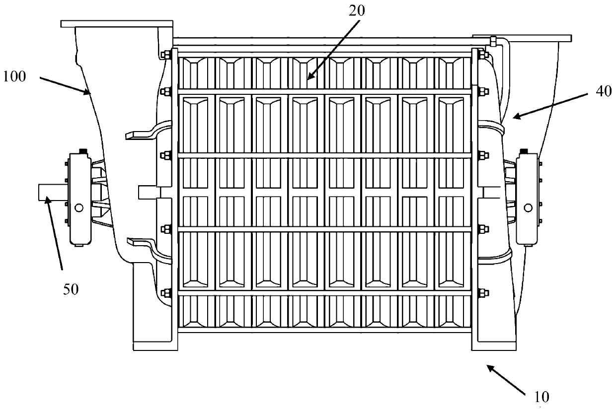
[0045] See figure 1 The shown centrifugal blower 10 with high aerodynamic efficiency includes a rotating main shaft 50 connected to the rotating drive unit (not shown in the figure), an air inlet housing 100 integrally connected with the rotating main shaft, and installed in the middle shell The multistage impeller 30 in the body 20 ( figure 1 impeller not shown) and exhaust housing 40;
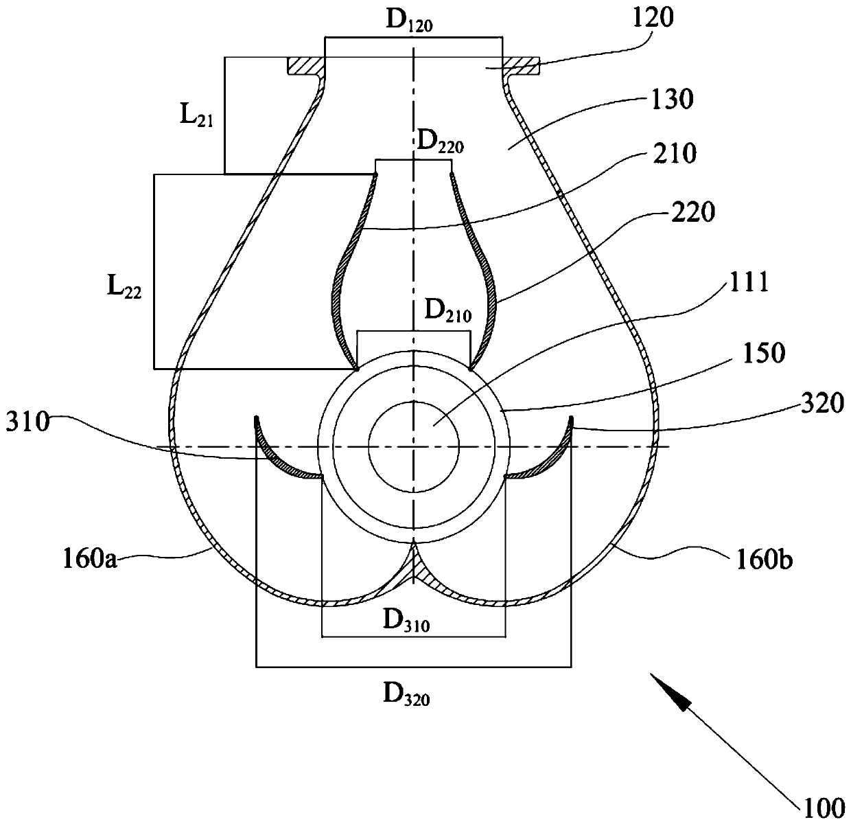
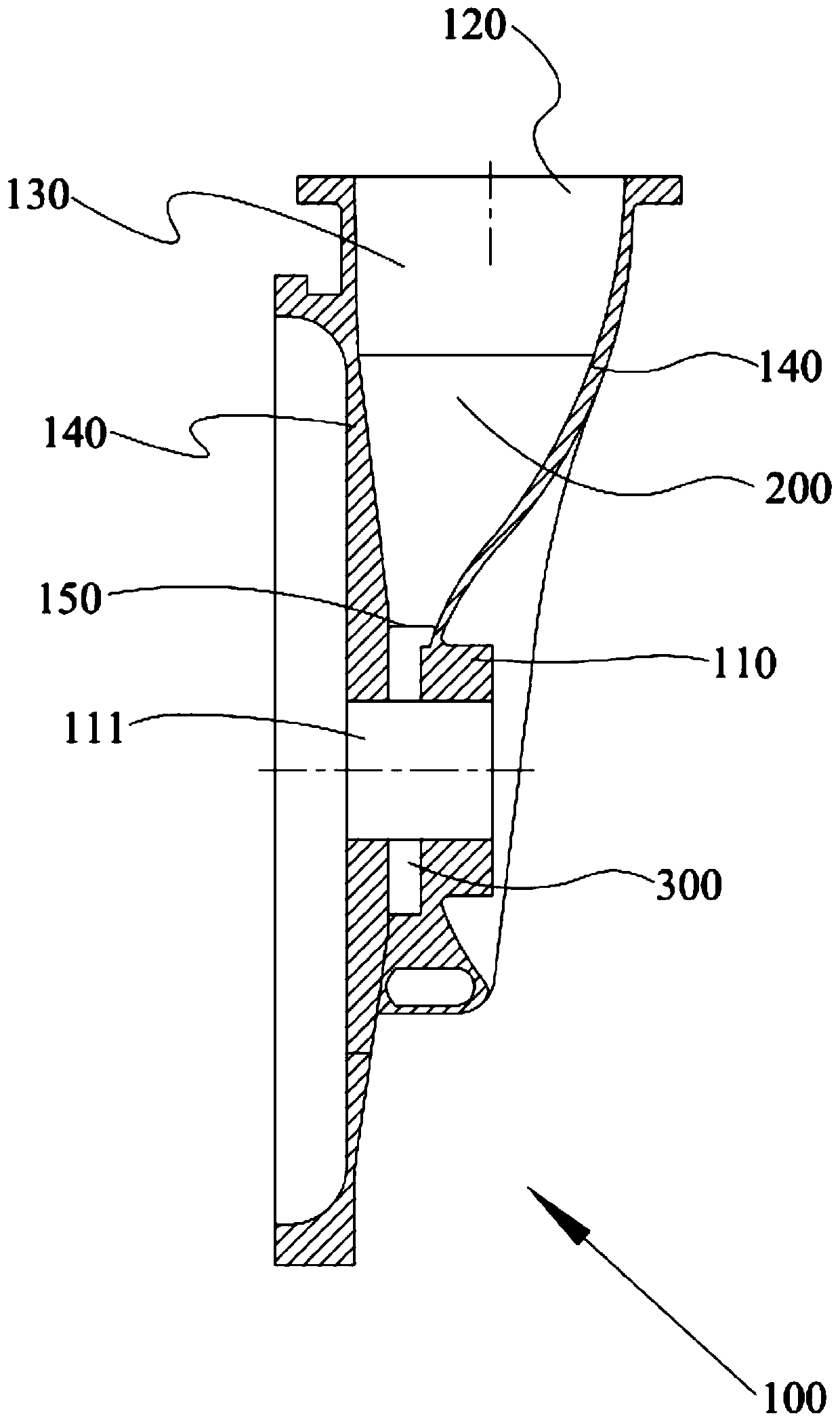
[0046] see further figure 2 and image 3 The air intake casing 100 shown is installed and connected to the main shaft (not shown) of the centrifugal blower through the bearing housing 110 installed with bearings (not shown in the figure), and the air intake casing 100 is provided with an air inlet located above 120 and air intake channel 130, the air inlet 120 communicates with the gas compression unit of the centrifugal blower through the air intake channel 130; the air intake channel 130 is respectively provided with a symmetrical curved surface leading vane group 200 and a symmetrical ...
Embodiment 2
[0067] The remaining technical solutions of this embodiment 2 are the same as those of the above embodiment 1, the difference is only in the impeller structure, specifically, in this embodiment 2, please refer to Figure 12 and Figure 13 An impeller 30' is shown. The impeller 30' adopts an aluminum alloy integrally cast impeller disc 31' and several blades 32' located on the impeller disc. Each blade 32' is evenly distributed on the inner periphery of the impeller disc 31'. The impeller disc 31' is provided with a rotating shaft hole 33' fixedly connected to the rotating main shaft 50, an axial air inlet 34' communicating with the inlet flow passage, and a radial exhaust outlet 35' communicating with the outlet flow passage; , each vane 32' includes a forward vane section 32a' located at one end near the axial inlet 34' and a rearward vane section 32c' located at one end near the radial exhaust port 35', the forward vane section 32a' and the backward blade section 32c' are c...
PUM
 Abstract
Description
Claims
Application Information
 - R&D
- Intellectual Property
- Life Sciences
- Materials
- Tech Scout
- Unparalleled Data Quality
- Higher Quality Content
- 60% Fewer Hallucinations
Browse by: Latest US Patents, China's latest patents, Technical Efficacy Thesaurus, Application Domain, Technology Topic, Popular Technical Reports.
© 2025 PatSnap. All rights reserved.Legal|Privacy policy|Modern Slavery Act Transparency Statement|Sitemap|About US| Contact US: help@patsnap.com


