Supercharge Your Innovation With Domain-Expert AI Agents!

Optical fiber movable connector and using method thereof

A technology of movable connectors and swing connections, which is applied in the direction of light guides, optics, instruments, etc., can solve problems such as limited operating space, affecting work efficiency, and laborious plugging and unplugging, and achieves the effects of improving work efficiency, convenient connection, and ample operating space

Pending Publication Date: 2019-08-02
YOSHIHIRO COMM EQUIP GRP CO LTD
View PDF0 Cites 3 Cited by
  • Summary
  • Abstract
  • Description
  • Claims
  • Application Information

AI Technical Summary

Problems solved by technology

[0002] When the optical fiber is docked, it needs to be connected with a movable connector to achieve the function of extending the cable. Most of the existing movable connectors are assembled on a fixed frame, and then the fixed frame with multiple movable connectors is installed. In the cabinet, due to the complexity of the lines in the cabinet and the limited operating space provided, it is often difficult to insert and pull out the optical fiber on the active connector, which affects work efficiency

Method used


Image

  • Optical fiber movable connector and using method thereof
  • Optical fiber movable connector and using method thereof
  • Optical fiber movable connector and using method thereof

Examples


Embodiment Construction

[0025] Embodiments of the present invention will be further described in detail below in conjunction with the accompanying drawings and examples. The following examples are used to illustrate the present invention, but should not be used to limit the scope of the present invention.

[0026] In the description of the present invention, unless otherwise stated, the meaning of "plurality" is two or more; the terms "upper", "lower", "left", "right", "inner", "outer" , "front end", "rear end", "head", "tail", etc. indicate the orientation or positional relationship based on the orientation or positional relationship shown in the drawings, and are only for the convenience of describing the present invention and simplifying the description, rather than Nothing indicating or implying that a referenced device or element must have a particular orientation, be constructed, and operate in a particular orientation should therefore not be construed as limiting the invention. In the descrip...


PUM


Abstract

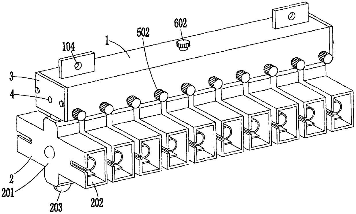
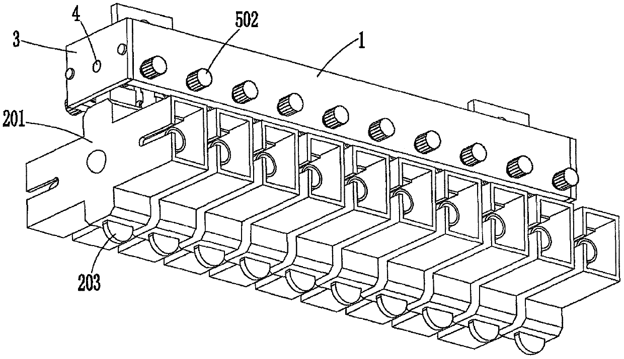
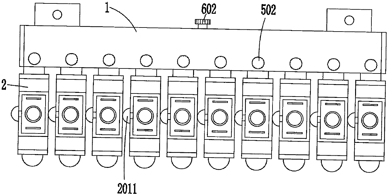
The invention discloses an optical fiber movable connector and a using method thereof. The optical fiber movable connector comprises a mounting cross frame and a plurality of movable connectors arranged at the bottom of the mounting cross frame in parallel, wherein the bottom of the mounting cross frame is provided with an accommodating cavity, and two ends of the accommodating cavity are providedwith end covers; each movable connector comprises a movable connector body, connecting ports arranged at the front side and the rear side of the movable connector body, a shifting piece arranged at the bottom of the movable connector body and a swing connecting rod arranged at the top of the movable connector body; the swing connecting rod extends into the accommodating cavity, a rotating shaft is arranged between the end covers at two ends, the swing connecting rod is hinged to the rotating shaft; the front sides and the rear sides of the swing connecting rod and the mounting cross frame areconnected through elastic resetting assemblies; a locking mechanism is arranged between the swing connecting rod and the top of the mounting cross frame. The optical fiber movable connector of the invention has the beneficial effects that: swing of the movable connector can be realized through a unique structure, the connection between the optical fiber and the movable connector is conveniently completed, and the working efficiency is improved.

Description

technical field [0001] The invention relates to the technical field of optical fiber active connectors, in particular to an optical fiber active connector and a use method. Background technique [0002] When the optical fiber is docked, it needs to be connected with a movable connector to achieve the function of extending the cable. Most of the existing movable connectors are assembled on a fixed frame, and then the fixed frame with multiple movable connectors is installed. In the cabinet, due to the complexity of the lines in the cabinet and the limited operating space, it is often difficult to insert and remove optical fibers on the active connector, which affects work efficiency. Contents of the invention [0003] The object of the present invention is to avoid the disadvantages of the prior art, and provide an optical fiber active connector and a usage method, thereby effectively solving the disadvantages of the prior art. [0004] In order to achieve the above object...

Claims


Application Information

Patent Timeline
Patent Type & Authority Applications(China)
IPC IPC(8): G02B6/38G02B6/40
CPCG02B6/3897G02B6/40
Inventor 邵明明闫立伟邵继保槐恩伟冯青凯
Owner YOSHIHIRO COMM EQUIP GRP CO LTD
Features
  • R&D
  • Intellectual Property
  • Life Sciences
  • Materials
  • Tech Scout
  • Unparalleled Data Quality
  • Higher Quality Content
  • 60% Fewer Hallucinations
Learn More