
Electric shock preventing connector and electric shock preventing connector with signal transmission function

An anti-electric shock and connector technology, applied in the parts, connections, circuits and other directions of the connecting device, can solve the problems of black burning, human electric shock accidents, and family scars of the parties concerned.

Inactive Publication Date: 2019-08-02
东莞市恩赞科技有限公司
View PDF0 Cites 0 Cited by
  • Summary
  • Abstract
  • Description
  • Claims
  • Application Information

AI Technical Summary

Problems solved by technology

[0004] At present, connectors for charging or charging and discharging connectors for electric vehicles, balance vehicles, twisting vehicles, unicycles, scooters, and scooters on the market are installed and fixed on their shells, but the positive and negative poles of the connectors Conductive parts are generally exposed directly outside
Although its connector is connected to the battery through an external power line, once the voltage of the battery exceeds 36V, it exceeds the safe voltage that the human body can withstand. Once a person accidentally touches the positive and negative conductive parts, it is easy to cause an electric shock to the human body ACCIDENT
We can see a lot of news reports on the Internet. When children accidentally touch the conductive parts of the connector with coins, keys or other metal materials when they are playing, the sparks splash instantly, and the coins, keys or other metal materials touch the conductive parts of the connector. The material was burnt black and the fingers were badly burned! Originally, childhood is a beautiful memory for everyone, but these shocking electric shock accidents have caused irreparable damage to the children throughout their lives, and caused scars that can never be erased to the families of the parties involved.

Method used


Image

  • Electric shock preventing connector and electric shock preventing connector with signal transmission function
  • Electric shock preventing connector and electric shock preventing connector with signal transmission function
  • Electric shock preventing connector and electric shock preventing connector with signal transmission function

Examples


Embodiment 1

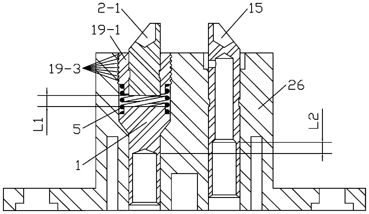
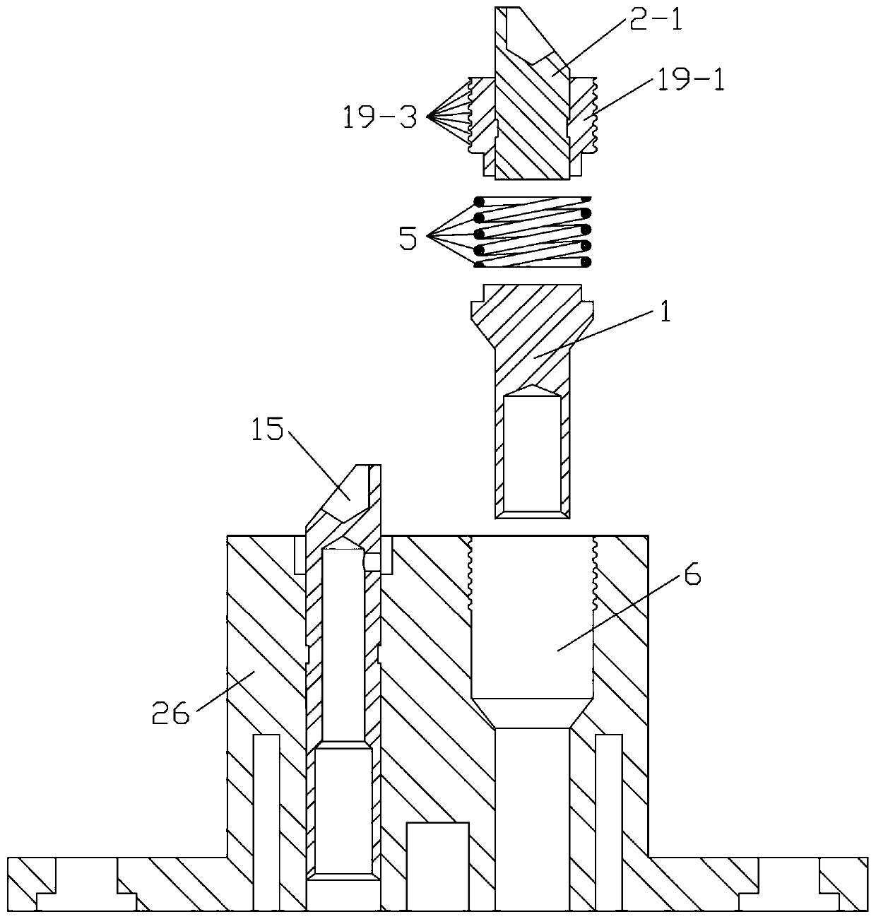
[0055] Such as figure 1 , figure 2 As shown, the anti-shock connector female head 26 is composed of a common female electrode 15, an insulating body, an electric-shock-proof front-end female electrode 1, a spring 5, and an electric-shock-proof rear-end female plug 19-1 with a welding wire gap; The anti-shock rear-end female plug 19-1 is composed of an electric-shock-proof rear-end female electrode 2-1 with a welding wire gap and an insulating shell; the common female electrode 15 is integrally injection-molded in the insulating main body, and the insulating main body has an insulating positioning groove 6. The insulation positioning groove 6 is located on the other side of the ordinary female electrode 15; the electric shock-proof front-end female electrode 1 is placed on the front end of the insulation positioning groove 6, and the spring 5 is placed on the electric shock-proof front-end female electrode 1 and the anti-shock electrode with a welding wire gap. Between the el...

Embodiment 2

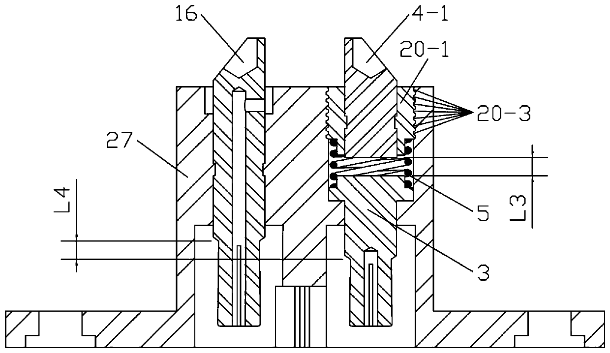
[0058] Such as Figure 7 As shown, the anti-shock anti-short-circuit connector female head 28 is composed of an anti-short-circuit female electrode 7, an insulating body, an electric-shock-proof front-end female electrode 1, a spring 5, and an electric-shock-proof rear-end female plug 19-1 with a welding wire gap; anti-short circuit The female electrode 7 is composed of a first female electrode 13-1, a fuse 21, a plastic protective case, and a second female electrode 13-3 with a welding wire gap; The anti-shock rear end female electrode 2-1 of the line gap is composed of an insulating shell; the anti-short circuit female electrode 7 is integrally injection-molded in the insulating main body, and the insulating positioning groove 6 is arranged in the insulating main body, and the insulating positioning groove 6 is located in the anti-short circuit female electrode The other side of the anti-shock front-end female electrode 1 is placed in the front end of the insulating position...

Embodiment 3

[0060] Such as Figure 9 As shown, the anti-shock anti-short-circuit connector female head 28 is composed of a first female electrode 13-1, a fuse 21, an anti-short-circuit rear-end female plug 22-1 with a welding wire gap, an insulating body, an electric-shock-proof front-end female electrode 1, and a spring 5. The anti-shock rear female plug 19-1 with a welding wire gap; the anti-short circuit rear female plug 22-1 with a welding wire gap is composed of a second female electrode 13-3 with a welding wire gap and a plastic shell; The electric-shock-proof rear-end female plug 19-1 with a welding wire gap is composed of an electric-shock-proof rear-end female electrode 2-1 with a welding wire gap and an insulating shell; the first female electrode 13-1 is integrally injection-molded in the insulating body , the rear end of the insulating body has an insulating column groove connected to the rear end inner hole of the first female electrode 13-1; after the fuse 21 is placed in th...


PUM


Abstract

The invention provides an electric shock preventing connector and an electric shock preventing connector with a signal transmission function. The electric shock preventing connector comprises an electric shock preventing connector female head, an electric shock preventing connector male head, an electric shock and short circuit preventing connector female head, an electric shock and short circuitpreventing connector male head, an electric shock preventing connector female head with both ends being capable of insertion, an electric shock preventing connector male head with both ends being capable of insertion, an electric shock and short circuit preventing connector female head with both ends being capable of insertion and an electric shock and short circuit preventing connector male headwith both ends being capable of insertion. The electric shock preventing connector with a signal transmission function comprises an electric shock preventing connector male head with a signal transmission function, an electric shock preventing connector male head with a signal transmission function, an electric shock and short circuit preventing connector female head with a signal transmission function, an electric shock and short circuit preventing connector male head with a signal transmission function, an electric shock preventing connector female head with both ends being capable of insertion and a signal transmission function and an electric shock preventing connector male head with both ends being capable of insertion and a signal transmission function.

Description

[0001] Technical field: [0002] The invention relates to a connector, in particular to an anti-shock connector and an anti-shock connector with signal transmission function. [0003] Background technique: [0004] At present, connectors for charging or charging and discharging connectors for electric vehicles, balance vehicles, twisting vehicles, unicycles, scooters, and scooters on the market are installed and fixed on their shells, but the positive and negative poles of the connectors Conductive parts are generally directly exposed outside. Although its connector is connected to the battery through an external power line, once the voltage of the battery exceeds 36V, it exceeds the safe voltage that the human body can withstand. Once a person accidentally touches the positive and negative conductive parts, it is easy to cause an electric shock to the human body ACCIDENT. We can see a lot of news reports on the Internet. When children accidentally touch the conductive parts ...

Claims


Application Information

Patent Timeline
IPC IPC(8): H01R13/71H01R13/696H01R13/502H01R13/42H01R13/10H01R13/04
CPCH01R13/04H01R13/10H01R13/42H01R13/502H01R13/696H01R13/71
Inventor 杨小伊
Owner 东莞市恩赞科技有限公司
Learn More