A continuous capping device for automatic assembly of power distribution cabinets

A technology for automatic assembly and power distribution cabinets, applied in switchgear, electrical components, etc., can solve the problem of inability to carry out continuous assembly work, and achieve the effects of fast locking, strong work continuity, and high productivity output.

Active Publication Date: 2020-05-26
国网甘肃省电力公司甘南供电公司
View PDF5 Cites 0 Cited by
  • Summary
  • Abstract
  • Description
  • Claims
  • Application Information

AI Technical Summary

Problems solved by technology

[0005] The purpose of the present invention is to address the deficiencies of the prior art, by setting an automatic capping mechanism, using the lifting assembly to cooperate with the tightening assembly, to realize the upper loading of the zero line and the continuous transmission of the bottom plate, and automatically complete the tightening of the zero line, thereby solving the problem. Solved the technical problem that when assembling the neutral line with the switch and the wiring board, it is necessary to stop the machine to tighten the screws, and it is impossible to carry out continuous assembly work

Method used


Image

  • A continuous capping device for automatic assembly of power distribution cabinets
  • A continuous capping device for automatic assembly of power distribution cabinets
  • A continuous capping device for automatic assembly of power distribution cabinets

Examples


Embodiment 1

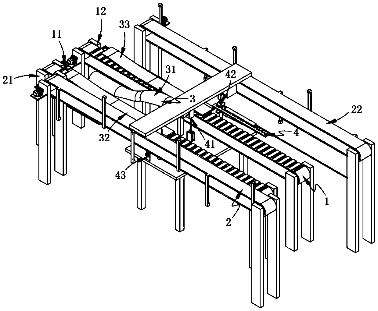
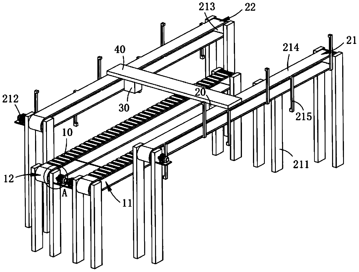
[0075] Such as figure 1 As shown, a continuous capping equipment for automatic assembly of power distribution cabinets, including:

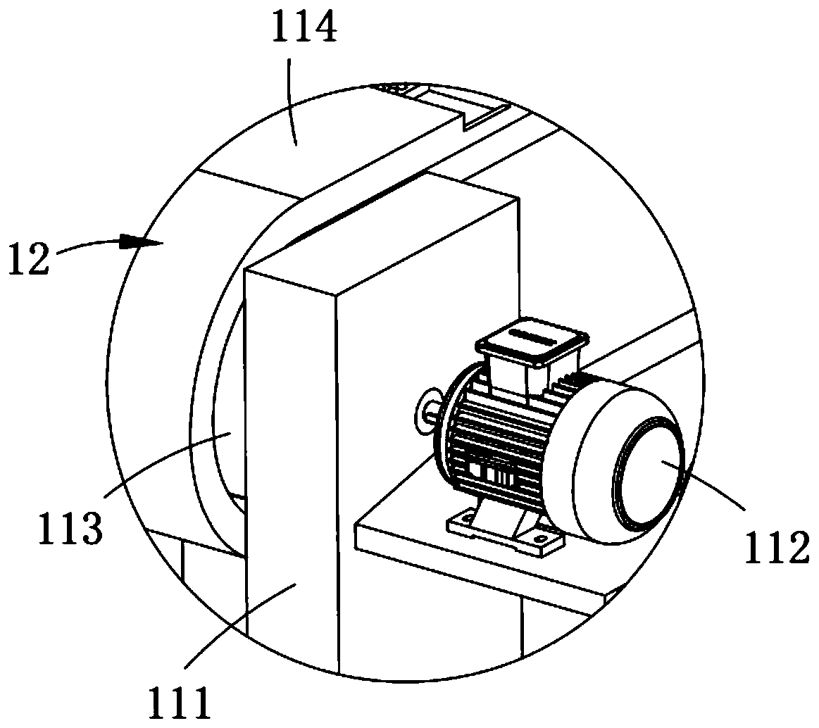
[0076] The first conveying mechanism 1, the first conveying mechanism 1 comprises a left conduction assembly a11 and a right conduction assembly a12 arranged side by side along the width direction of the left conduction assembly a11;

[0077] The second conveying mechanism 2, the second conveying mechanism 2 includes the left conduction assembly b21 arranged outside the left conduction assembly a11 and arranged side by side along the width direction of the left conduction assembly b21 and arranged on the right conduction assembly The right conductive component b22 outside the component a12;

[0078] Combined upper body mechanism 3, the combined upper body mechanism 3 includes an upper arch component 31 arranged between the left conductive component a11 and the right conductive component a12, respectively installed on the left conductive componen...

Embodiment 2

[0133] Such as Figure 4 , Figure 5 As shown, the components that are the same as or corresponding to those in the first embodiment are marked with the corresponding reference numerals in the first embodiment. For the sake of simplicity, only the differences from the first embodiment will be described below. The difference between this embodiment two and embodiment one is:

[0134] further, such as Figure 4 , Figure 5 As shown, both the positioning assembly a32 and the positioning assembly b33 include:

[0135] A stopper 321, the stopper 321 includes a support bar 3211 fixedly arranged on the bracket a111 and a positioning plate 3212 fixedly connected with the support bar 3211 and positioned directly above the belt a114, the positioning The plate 3212 is composed of two parts, the first half is arranged obliquely downward, the second half is arranged parallel to the belt a114, the upper end of the parallel part of the positioning plate 3212 is lower than the upper end o...


PUM


Abstract

The invention relates to continuous nut tightening equipment for automatic assembly of a distribution cabinet, which comprises a first conveying mechanism, a second conveying mechanism, a combined mounting mechanism and an automatic nut tightening mechanism, wherein the first conveying mechanism includes a left conduction transporting assembly a and a right transporting assembly a; the second conveying mechanism includes a left transporting assembly b and a right transporting assembly b; the combined mounting mechanism includes an upwarping assembly, a positioning assembly a and a positioningassembly b, the upwarping assembly is arranged between the left transporting assembly a and the right transporting assembly a, and the positioning assembly a and the positioning assembly b are respectively installed on the left transporting assembly a and the right transporting assembly a and are symmetrically arranged along the length direction of the upwarping assembly; and the automatic nut tightening mechanism includes a lifting assembly, tightening assemblies and limiting assemblies, the lifting assembly is arranged at the output end of the upwarping assembly, the tightening assemblies are symmetrically arranged at two sides of the upwarping assembly and are installed on the upwarping assembly, and the limiting assemblies are arranged at the front sides of the tightening assemblies and are in intermittent contact with the tightening assemblies. The continuous nut tightening equipment solves a technical problem that the machine needs to stop to tighten screws when a zero line is assembled with a switch and a wiring board and cannot carry out continuous assembly work.

Description

technical field [0001] The invention relates to the technical field of power distribution cabinet materials, in particular to a continuous capping device for automatic assembly of power distribution cabinets. Background technique [0002] The power distribution cabinet is used to control the mechanical equipment. The components in the power distribution cabinet, as well as the components and the mechanical equipment, are connected by wires or data cables. The connection methods are mainly welding and plug connections. [0003] The patent document with the patent number CN204615196U discloses a new type of power distribution cabinet, including a box body, a distribution board, and a wiring board. The distribution board and the wiring board are all installed in the box, and the wiring board is located The rear side of the box body, the front end of the box is equipped with a box door, a wire wheel plate is arranged between the wiring board and the distribution board, the wire ...

Claims


Application Information

Patent Timeline
Patent Type & Authority Patents(China)
IPC IPC(8): H02B3/00
CPCH02B3/00
Inventor 王子轩黄任宁王锋陈建清
Owner 国网甘肃省电力公司甘南供电公司
Why Eureka
Try Eureka