
A large-diameter thin-wall back-sealing structure counter-wheel spinning device based on edge constraints

An edge-constrained, large-diameter technology, applied in the field of large-diameter thin-walled back-sealing structure counter-wheel spinning devices, can solve problems such as complex spinning tracks, achieve low workshop space requirements, facilitate manual observation, and shorten the production cycle.

Active Publication Date: 2021-01-29
HARBIN INST OF TECH
View PDF11 Cites 0 Cited by
  • Summary
  • Abstract
  • Description
  • Claims
  • Application Information

AI Technical Summary

Problems solved by technology

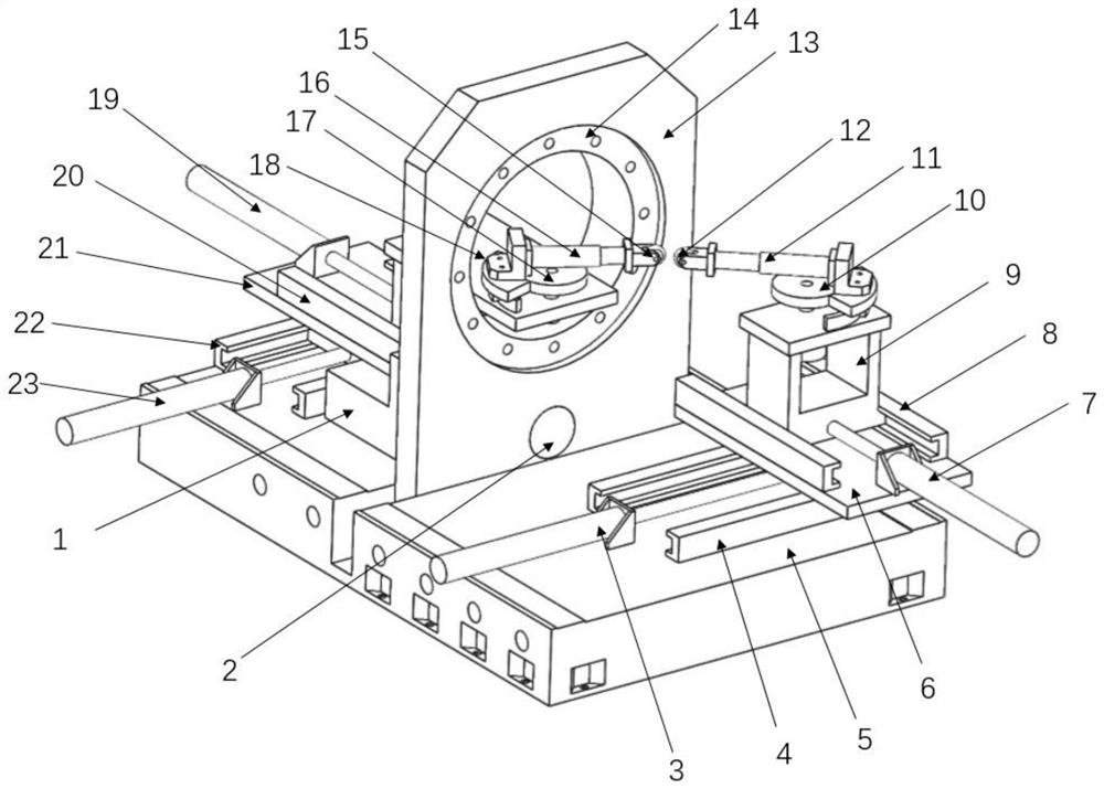
[0003] The object of the present invention is to provide a large-diameter thin-wall back-sealing structure wheel spinning device based on edge constraints, to solve the problems in the prior art above, adopt the feeding method from the edge to the center, and the inner and outer wheels pass through independently The horizontal movement of the horizontal guide rail and the vertical movement of each vertical guide rail are combined to realize the precise forming of the complex spinning track, thus breaking through the difficult problem of complex large-scale thin-walled back cover structure

Method used


Image

  • A large-diameter thin-wall back-sealing structure counter-wheel spinning device based on edge constraints
  • A large-diameter thin-wall back-sealing structure counter-wheel spinning device based on edge constraints
  • A large-diameter thin-wall back-sealing structure counter-wheel spinning device based on edge constraints

Examples


Embodiment Construction

[0026] The following will clearly and completely describe the technical solutions in the embodiments of the present invention with reference to the accompanying drawings in the embodiments of the present invention. Obviously, the described embodiments are only some, not all, embodiments of the present invention. Based on the embodiments of the present invention, all other embodiments obtained by persons of ordinary skill in the art without making creative efforts belong to the protection scope of the present invention.

[0027] The object of the present invention is to provide a large-diameter thin-wall back-sealing structure wheel spinning device based on edge constraints, to solve the problems in the prior art above, adopt the feeding method from the edge to the center, and the inner and outer wheels pass through independently The horizontal movement of the horizontal guide rail and the vertical movement of each vertical guide rail are combined to realize the precise forming ...


PUM


Abstract

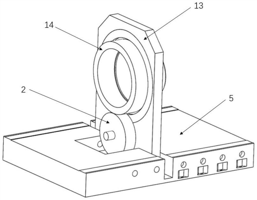
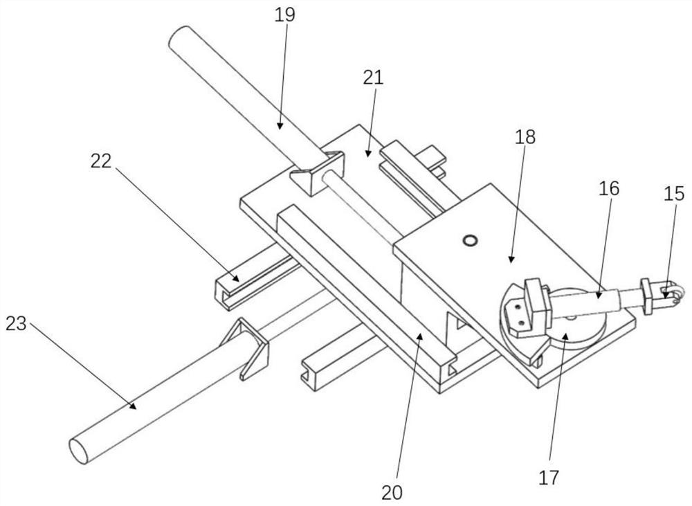
The invention discloses a large-diameter thin-wall sealing structure opposite roller spinning device based on edge constraint. The problems that existing die spinning equipment is high die cost, poorin universality and long in manufacturing period are solved. The large-diameter thin-wall opposite roller spinning device adopts a horizontal structure, transverse slide seats of an inner spinning roller mechanism and an outer spinning roller mechanism are installed on guide rails, and the displacement of the transverse slide seats is adjusted by two independently-controlled hydraulic cylinders; longitudinal guide rails of the inner spinning roller mechanism and the outer spinning roller mechanism are installed on the transverse slide seats correspondingly, longitudinal slide seats are connected with the longitudinal guide rails and controlled by the independent hydraulic cylinders, and accordingly, it is achieved that spinning rollers do compound motion in a plane; and the angle of the inner spinning roller and the angle of the outer spinning roller are controlled by a gear and a rack. A spinning machine seat is provided with a fixing groove, and the fixing groove is used for installing a rotary disc fixing seat; the rotary disc fixing seat is provided with a round opening which is used for installing a blank fixing rotary disc, and a blank is fixed to the blank fixing rotary discthrough a bolt; and a gear box and a motor are installed in the position, on one side of the rotary disc fixing set, of the spinning machine seat. The large-diameter thin-wall sealing structure opposite roller spinning device based on edge constraint is used for spinning forming of large-size sealing components.

Description

technical field [0001] The invention relates to the technical field of wheel spinning devices, in particular to a wheel spinning device with a large-diameter thin-walled back cover structure based on edge constraints. Background technique [0002] The spinning forming process has unique advantages in the forming of thin-walled bottom cover structures compared with welding and deep drawing due to its advantages of simple mold, flexible process, and wide adaptability. It is currently widely used in conical covers, spherical heads, curved busbar components, etc. Manufacture of products. Most of the traditional spinning forming processes require spinning mandrels, but when the structure size of the back cover is large, the mandrelless spinning process is widely used due to its low cost and short manufacturing cycle, such as the large head parts in the petrochemical industry A large number of coreless one-step and two-step spinning methods are used. However, the current head sp...

Claims


Application Information

Patent Timeline
Patent Type & Authority Patents(China)
IPC IPC(8): B21D22/14
CPCB21D22/14
Inventor 徐文臣陈家轩单德彬矫健陈宇韩越
Owner HARBIN INST OF TECH
Learn More