
Position-adjustable inner plate positioning mechanism for stamping parts in cold-punching and edge-coating processes

A positioning mechanism and cold stamping technology, applied in the field of mechanical equipment, can solve problems such as scraping workpieces, difficulty in adjusting the position of positioning pins for debuggers, misalignment of inner plates, etc., to ensure relative position accuracy, solve difficulty in picking parts, and reduce debugging. effect of difficulty

Pending Publication Date: 2019-08-06
格致汽车科技股份有限公司
View PDF0 Cites 0 Cited by
  • Summary
  • Abstract
  • Description
  • Claims
  • Application Information

AI Technical Summary

Problems solved by technology

In this positioning method, after the positioning pin is installed, it will cause difficulties for the commissioning personnel to adjust the position of the positioning pin.
If the position of the positioning pin is slightly deviated, the inner plate will be misaligned and the workpiece will be severely scratched

Method used


Image

  • Position-adjustable inner plate positioning mechanism for stamping parts in cold-punching and edge-coating processes
  • Position-adjustable inner plate positioning mechanism for stamping parts in cold-punching and edge-coating processes
  • Position-adjustable inner plate positioning mechanism for stamping parts in cold-punching and edge-coating processes

Examples


Embodiment Construction

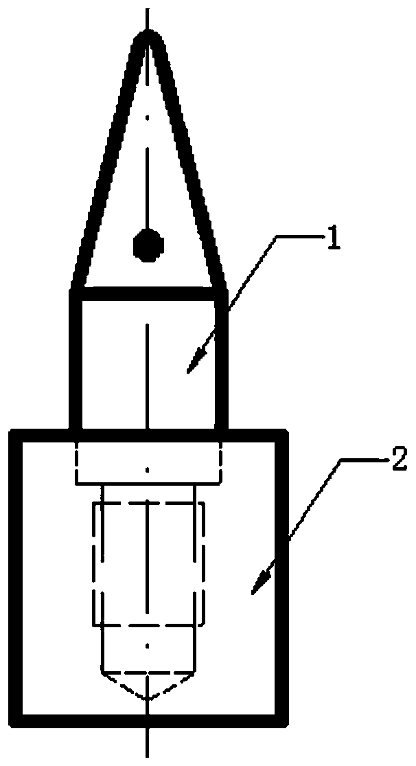
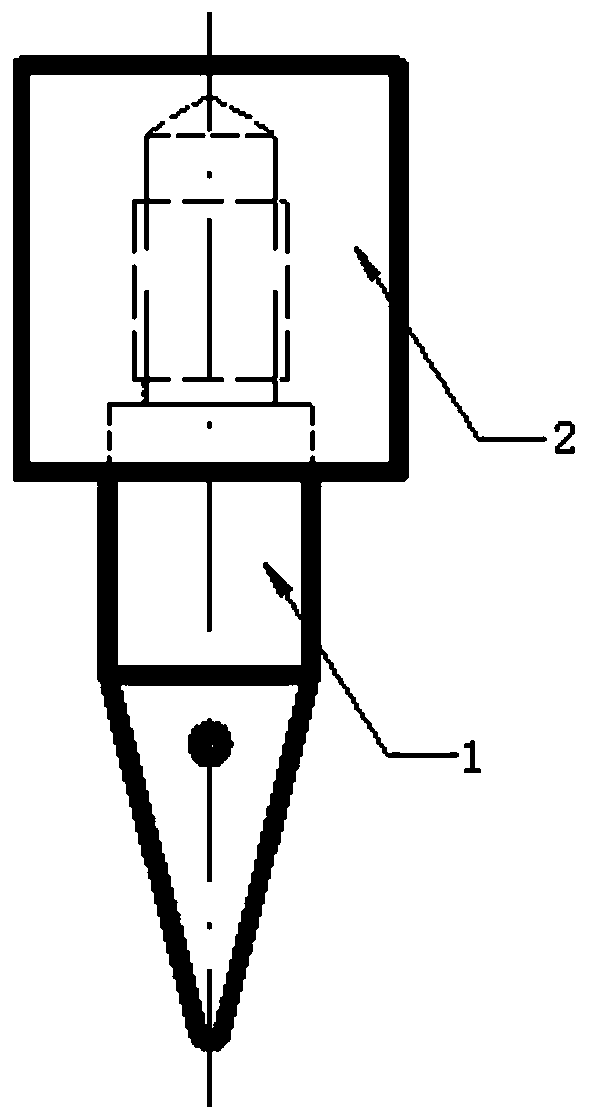
[0015] refer to Figure 7 , The positioning mechanism of the present invention includes a flat L-shaped adjustment seat 5 installed at the lower end of the upper mold. The vertical Z-shaped positioning pin frame 3 that can adjust the position relatively to the adjusting seat in a small amount, the adjusting gasket 4 between the adjusting block 5 and the positioning pin seat 3, the tightening screw between the adjusting block 5 and the positioning pin seat 3, and the positioning The flat part of the Z-shaped upper end of the pin seat 3 is located in the inner corner of the L-shaped adjustment block 5. There are fixing screw holes and positioning pin holes on the adjustment block 5. The pin is positioned at the lower end of the upper die. There are two mutually perpendicular flat screw holes on the adjustment block 5. The flat part of the Z-shaped upper end of the positioning pin seat 3 has a threaded hole opposite to the flat screw hole of the adjustment block 4. The tightenin...


PUM

PropertyMeasurementUnit
thicknessaaaaaaaaaa
thicknessaaaaaaaaaa
thicknessaaaaaaaaaa

Abstract

The invention discloses a position-adjustable inner plate positioning mechanism for stamping parts in cold-punching and edge-coating processes. The position-adjustable inner plate positioning mechanism comprises a transverse L-shaped adjusting base which is mounted at the lower end of an upper die, a vertical Z-shaped positioning pin rack which can slightly adjust the position relative to the adjusting base, an adjusting gasket which is arranged between an adjusting block and a positioning pin base, and a tightening screw rod which is arranged between the adjusting block and the positioning pin base, wherein a transverse part of a Z-shaped upper end of the positioning pin base is positioned in an inner corner of the L-shaped adjusting block; the adjusting block is fixed to the lower end face of the upper die by using a screw rod; the tightening screw rod which transversely passes through the adjusting block and is screwed into the positioning pin base can be used for tightening the positioning pin base on the adjusting block; a transverse part of a Z-shaped lower end of the positioning pin base is mounted on an inner plate positioning pin which is pointed downwards; and a spring plunger is mounted aside the inner plate positioning pin. The position-adjustable inner plate positioning mechanism disclosed by the invention has the advantages that the precision of opposite positionsof the stamping parts is ensured, the situations that malposition of an inner plate and scrapping of workpieces are caused when deviation of the position of the positioning pin occurs are prevented,and the problem that the parts are difficultly taken after an edge-coating operation is carried out completely is solved and the debugging difficulty of debugging personnel is reduced.

Description

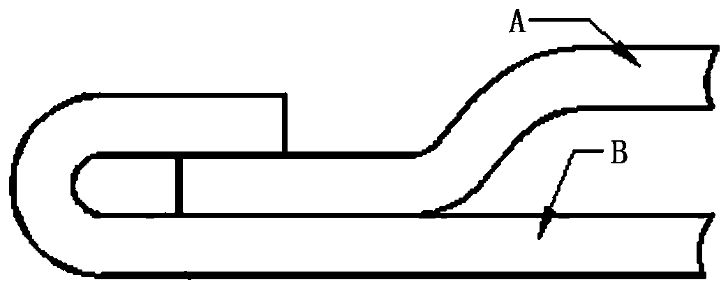
technical field [0001] The invention belongs to the field of mechanical equipment, and in particular relates to a positioning device for a processed piece in a cold stamping hemming die of a sheet metal piece. Background technique [0002] The hemming process of automobile sheet metal parts is generally used for the inner and outer panels of automobile assembly parts (usually opening and closing parts, sometimes including roof covers with sunroofs, such as automobile doors). After the upper flanging or the lower flanging is flattened by bending, the assembly process that connects the inner and outer plates of the part, and the edge wrapping process figure 1 . The mold that completes this process is called a hemming mold. It can be seen from the schematic diagram that in the mold production process, the inner plate A and the outer plate B are stacked together, the inner plate is on top and the outer plate is on the bottom. In order to ensure the relative position accuracy ...

Claims


Application Information

Patent Timeline
Patent Type & Authority Applications(China)
IPC IPC(8): B21D39/02B21D43/00
CPCB21D39/021B21D43/003
Inventor 王中林贵森刘继彦赵晓峰
Owner 格致汽车科技股份有限公司
Learn More