
Quick positioning die for automobile electronic component machining

A technology for electronic components and positioning molds, applied in electrical components, electrical components, manufacturing tools, etc., can solve problems such as poor stability and slow positioning speed, and achieve the effect of improving stability, improving accuracy and facilitating replacement.

Inactive Publication Date: 2019-08-06
天津裕隆宏达机械设备有限公司
View PDF1 Cites 3 Cited by
  • Summary
  • Abstract
  • Description
  • Claims
  • Application Information

AI Technical Summary

Problems solved by technology

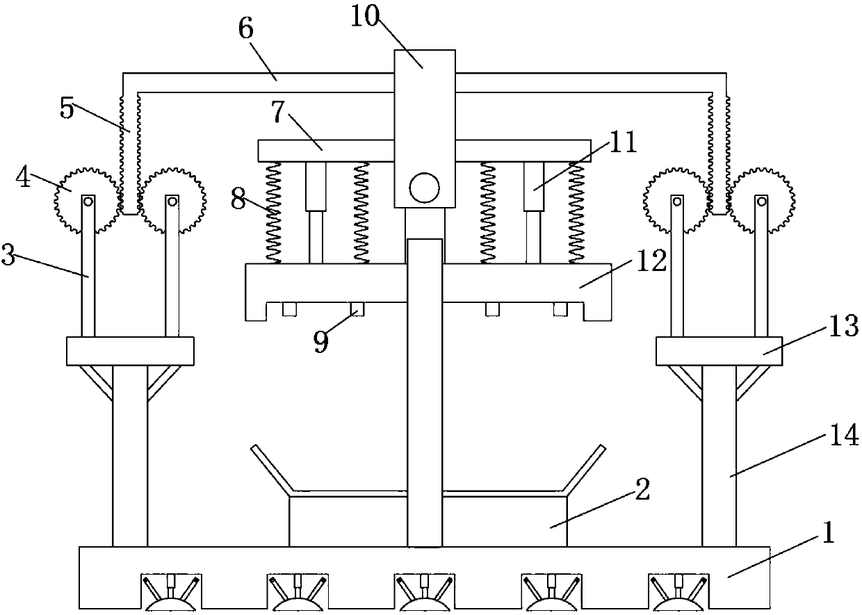
[0005] Aiming at the deficiencies of the prior art, the present invention provides a rapid positioning mold for processing automotive electronic components. The advantages of positioning solve the problem of the slow positioning speed of the rapid positioning molds used in the processing of electronic components in the market. Generally, multiple manual operations are used at the same time, and the positioning column is assisted, so that positioning can be achieved, and the existing positioning molds are stable. poor

Method used


Image

  • Quick positioning die for automobile electronic component machining
  • Quick positioning die for automobile electronic component machining

Examples


Embodiment Construction

[0022] The following will clearly and completely describe the technical solutions in the embodiments of the present invention with reference to the accompanying drawings in the embodiments of the present invention. Obviously, the described embodiments are only some, not all, embodiments of the present invention.

[0023] In describing the present invention, it should be understood that the terms "upper", "lower", "front", "rear", "left", "right", "top", "bottom", "inner", " The orientation or positional relationship indicated by "outside", etc. is based on the orientation or positional relationship shown in the drawings, and is only for the convenience of describing the present invention and simplifying the description, rather than indicating or implying that the referred device or element must have a specific orientation, so as to Specific orientation configurations and operations, therefore, are not to be construed as limitations on the invention.

[0024] refer to Figure ...


PUM


Abstract

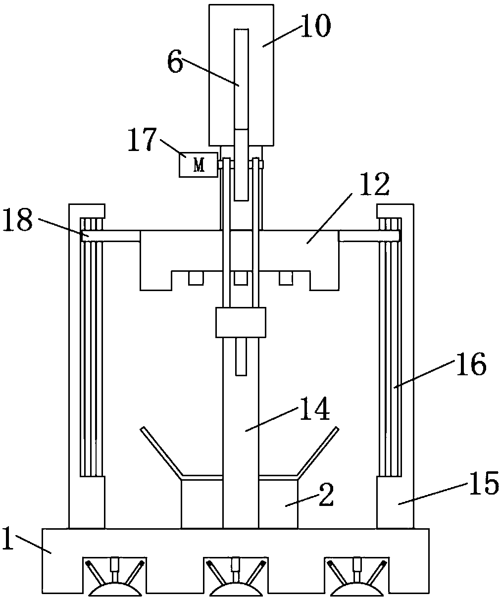
The invention discloses a quick positioning die for automobile electronic component machining. The quick positioning die comprises a base; two mounting frames are symmetrically arranged on the base; four supporting plates are symmetrically arranged on each mounting frame; a gear is arranged on the two supporting plates at the corresponding positions through a rotating shaft; a bidirectional rack is jointly engaged between the two gears on the same mounting frame; each bidirectional rack is fixedly connected with a connecting rod; the two connecting rods are jointly provided with a fixing block; the fixing block is rotationally connected with an upper die; the fixing block is symmetrically provided with two limiting plates; each limiting plate is fixedly connected with an electric telescopic rod, and an annular groove is formed in the lower surface of the upper die. The quick positioning die is ingenious in structure, convenient to use, high in stability, capable of achieving positioning without simultaneous operation of a plurality of workers and assistance of positioning columns, and worthy of popularization.

Description

technical field [0001] The invention relates to the technical field of production equipment for automotive electronic components, in particular to a rapid positioning mold for processing automotive electronic components. Background technique [0002] As the electronic level of automobiles is getting higher and higher, more and more electronic components need to be installed. Positioning molds are required in the processing of automotive electronic components. The positioning speed of existing molds for electronic components is slow. Generally, multiple manual operations are used at the same time, and the assistance of positioning columns is required for positioning, and the stability of existing positioning molds is relatively poor. [0003] After searching, the Chinese patent authorization number CN 206263823U discloses a quick positioning mold for processing electronic components, including a base, and vertical support plates are welded on both sides of the top of the base...

Claims


Application Information

Patent Timeline
Patent Type & Authority Applications(China)
IPC IPC(8): B25B11/00H05K13/04
CPCB25B11/00H05K13/04
Inventor 赵福水白亦坚
Owner 天津裕隆宏达机械设备有限公司
Learn More