Method for preventing perforating injury of optical cable of tubular column in horizontal well

A technology for horizontal wells and pipe strings, applied in the field of perforating oil and gas wells, can solve the problems of irregular twisting of casing, inability to accurately avoid optical fibers, and inconsistency between optical fiber positions and preset conditions, so as to avoid unnecessary effect of loss

Active Publication Date: 2019-08-06
CHONGQING UNIVERSITY OF SCIENCE AND TECHNOLOGY
View PDF12 Cites 3 Cited by
  • Summary
  • Abstract
  • Description
  • Claims
  • Application Information

AI Technical Summary

Problems solved by technology

However, the long-distance lowered casing will be irregularly twisted, so that the actual direction and position of the optical fiber in the wellbore are inconsistent with t

Method used


Image

  • Method for preventing perforating injury of optical cable of tubular column in horizontal well
  • Method for preventing perforating injury of optical cable of tubular column in horizontal well
  • Method for preventing perforating injury of optical cable of tubular column in horizontal well

Examples


Embodiment 1

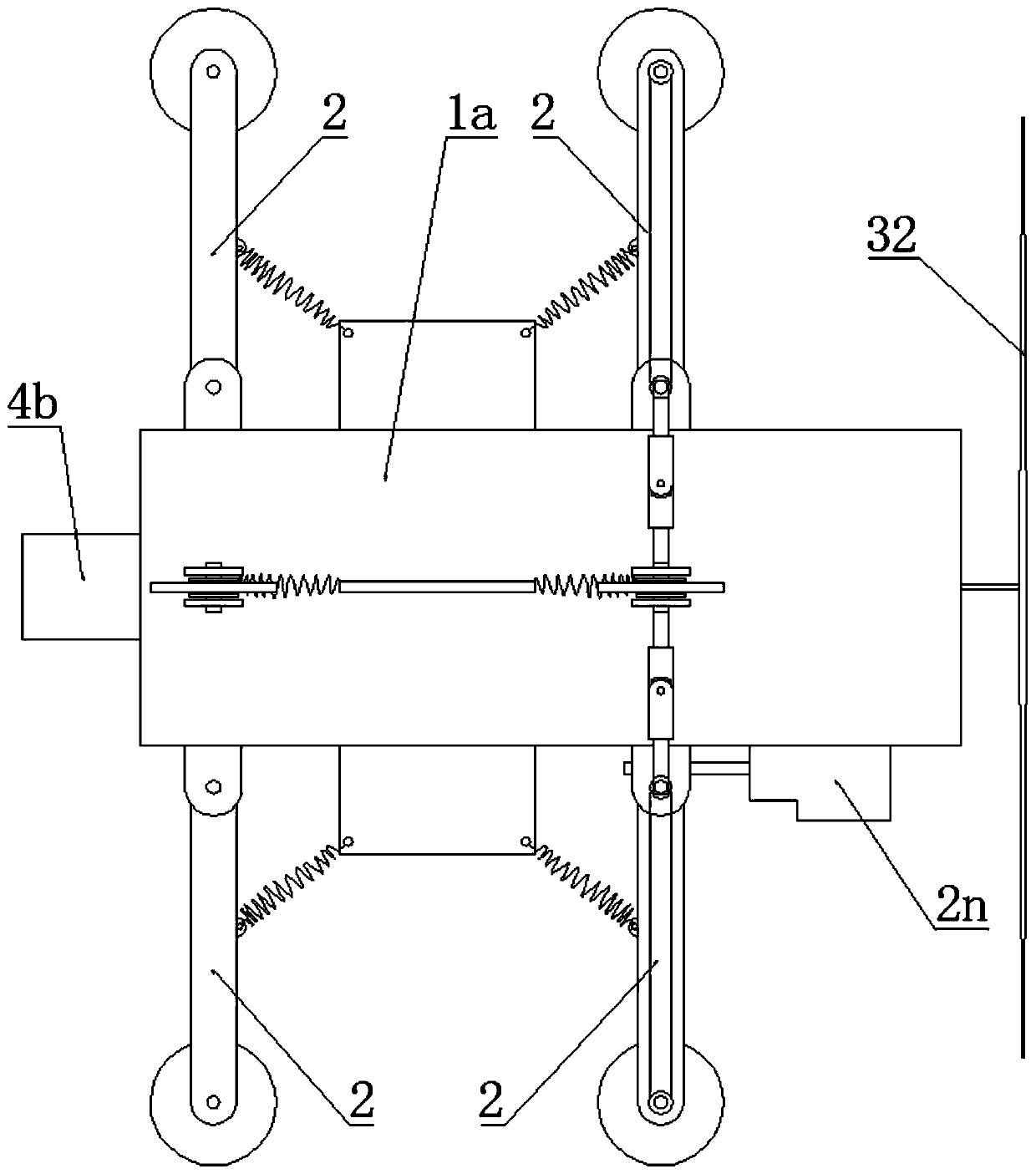
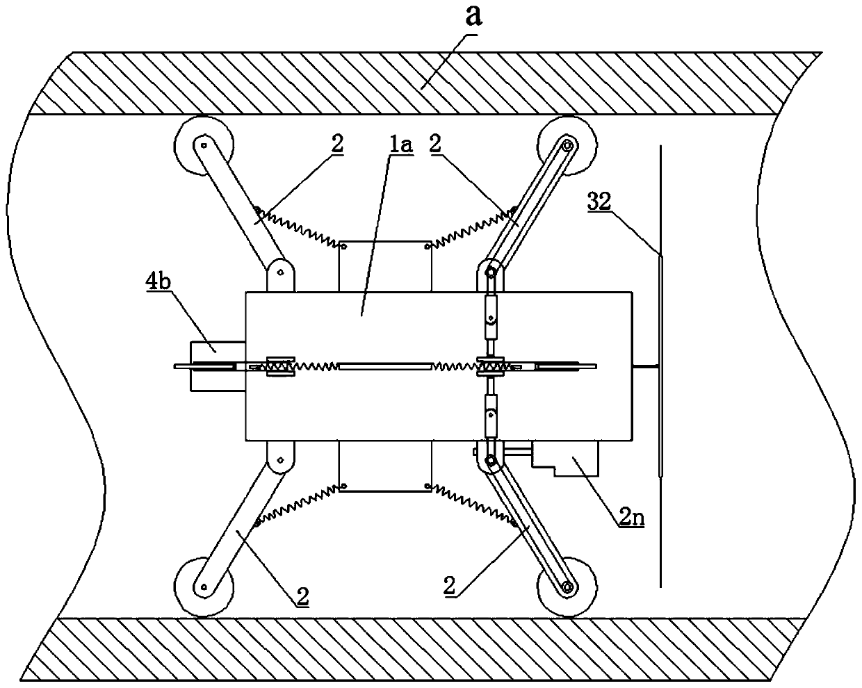
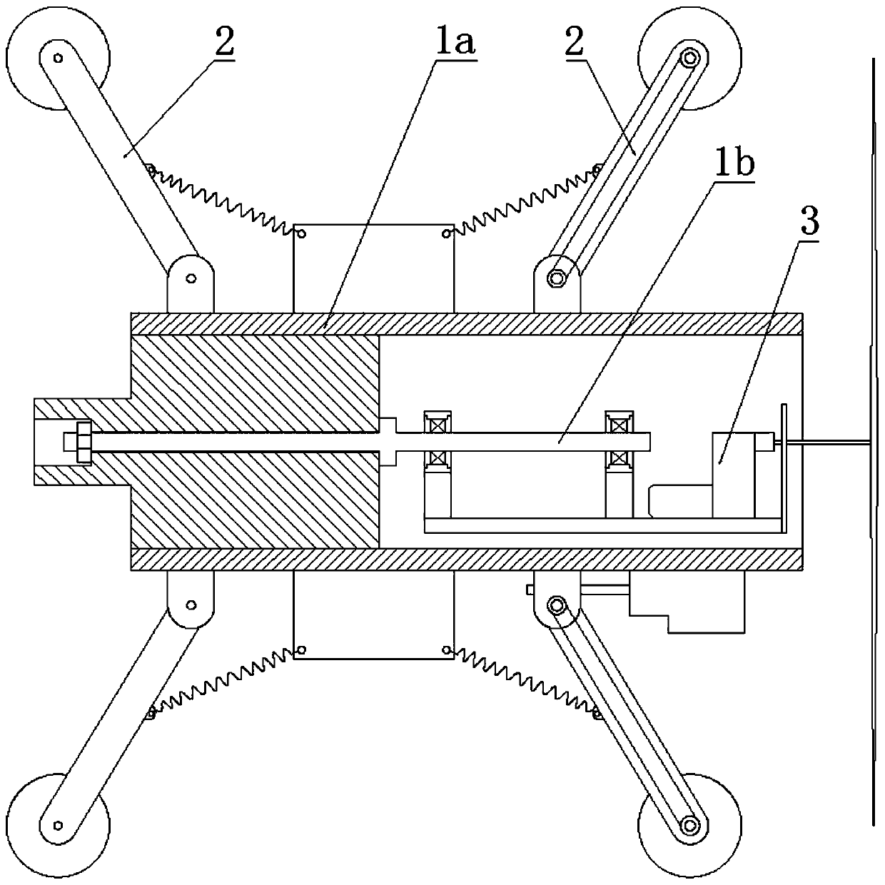
[0067] Such as Figure 1-7 As shown, a horizontal well downhole magnetic marker positioning device includes a horizontal support sleeve 1a, the outer wall of the support sleeve 1a is provided with a walking mechanism 2, and the support sleeve 1a is horizontally provided with a hoisting shaft 1b. A gravity eccentric assembly is movable on the shaft 1b, and a marking assembly 3 is arranged on the gravity eccentric assembly. Described seek assembly 3 comprises low-speed motor 31, and the output shaft of this low-speed motor 31 is arranged horizontally, and the output shaft of this low-speed motor 31 is fixedly connected with pointing magnetic needle 32, and the output shaft of described low-speed motor 31 and described pointing magnetic needle 32 mutually vertical.

[0068] The gravity eccentric assembly includes an eccentric weight plate 1c, the eccentric weight plate 1c is located below the hoisting shaft 1b, two lifting lugs 1d are fixed on the upper surface of the eccentric ...

Embodiment 2

[0087] A method for preventing the perforation damage of the optical cable of the horizontal well string is carried out according to the following steps:

[0088] Step 1, arranging the column a and the optical cable c;

[0089] Connect the pipe joints a1 with magnetic mark seats b on the outer wall in sequence along the same direction to form the pipe column a, the magnetic mark seats b are distributed at equal intervals on the pipe column a, and the optical cable c along the The length direction of the pipe string a is fixed on the magnetic mark base b, the optical cable c is lowered into the horizontal well synchronously with the pipe string a, and all magnetic poles of the same name of the magnetic mark base b face the pipe string a the pipe core line;

[0090] Step two, cementing;

[0091] Step 3: Detect and record the direction information of the downhole optical cable;

[0092] Such as figure 1 As shown, the positioning device d in the first embodiment is sent into t...

Embodiment 3

[0103] The difference with Embodiment 2 is that when determining the distribution diagram of the optical cable in step 3, such as Figure 10 , project the two adjacent magnetic marker seats b of A and B onto the same column section, in the figure, A' is obtained by projecting A onto the section where B is located, and an interposed between A' and B The central angle of is recorded as the angle θ of the cable area, and the area of ​​the cylindrical surface between A and B corresponding to the angle θ of the cable area is recorded as the cable section f.

[0104] Such as Figure 11 , and then obtain the continuously distributed optical cable sections f according to the position information of the magnetic marker seat b, and combine all the optical cable sections f sequentially to obtain an optical cable area map.

[0105] The denser the above-mentioned magnetic marker seats b are arranged, the more accurate the optical cable area map drawn after detection will be.

[0106] Fur...


PUM


Abstract

The invention discloses a method for preventing the perforating injury of an optical cable of a tubular column in a horizontal well. The method includes the steps that first, the tubular column with amagnetic marker seat on the outer wall is arranged in the well, and meanwhile, the optical cable is fixed to the magnetic marker seat in the length direction of the tubular column; second, well cementation is conducted; third, a positioning device is used for extending into the tubular column and moving along the tubular column, location information of the magnetic marker seat are detected and recorded to obtain an optical cable trend distribution map; and fourth, a perforating device is lowered, and the optical cable at the target pipe section is avoided for perforating operation according to the optical cable trend distribution map. The method has the beneficial effects that the position of the magnetic marker seat is determined by arranging the magnetic marker seat and using the positioning device, distribution information of the optic cable outside the tubular column can be obtained, and the optical cable is prevented from being damaged during perforating operation.

Description

technical field [0001] The invention relates to the technical field of oil and gas well perforation operations, in particular to a method for preventing perforation damage of a horizontal well pipe string optical cable. Background technique [0002] In the process of oilfield development, it is necessary to know the detailed information on the characteristics and state of the fluid in the well. Optical fiber logging has the advantages of being insensitive to electromagnetic interference and able to withstand extreme conditions; it can perform continuous measurement along the wellbore during the entire production cycle, realizing Permanent monitoring of oil and gas wells, providing producers with detailed, comprehensive and accurate downhole production data. [0003] During the arrangement of downhole sensors and optical fibers, the optical fibers are usually fixed along the length of the casing, and the outer wall of the casing is provided with an optical fiber fixing device...

Claims


Application Information

Patent Timeline
IPC IPC(8): E21B47/00E21B43/119
CPCE21B47/00E21B43/119
Inventor 曲海刘营唐世茂张硕胡誉双
Owner CHONGQING UNIVERSITY OF SCIENCE AND TECHNOLOGY
Why Eureka
Try Eureka