Automatic laser marking device

A laser marking equipment and automatic technology, applied in the field of laser marking, can solve the problems of affecting the marking effect and insufficient fixing strength of the PCB board, and achieve the effect of preventing movement and improving the marking efficiency.

Pending Publication Date: 2019-08-09
江苏华锟智能科技有限公司
View PDF7 Cites 4 Cited by
  • Summary
  • Abstract
  • Description
  • Claims
  • Application Information

AI Technical Summary

Problems solved by technology

[0004] The object of the present invention is to provide a kind of automatic laser marking equipment, in order to solve the above-mentioned background when carrying out the automatic laser marking of PCB board, only one PCB board can be marked at a time, and the fixed strength of PCB board is insufficient , once it moves during the marking process, it will seriously affect the marking effect

Method used


Image

  • Automatic laser marking device
  • Automatic laser marking device
  • Automatic laser marking device

Examples


Embodiment Construction

[0032] The technical solutions in the embodiments of the present invention will be clearly and completely described below in conjunction with the accompanying drawings in the examples of the present invention. Obviously, the described embodiments are only some of the embodiments of the present invention, not all of them. Based on the embodiments of the present invention, all other embodiments obtained by persons of ordinary skill in the art without creative efforts fall within the protection scope of the present invention.

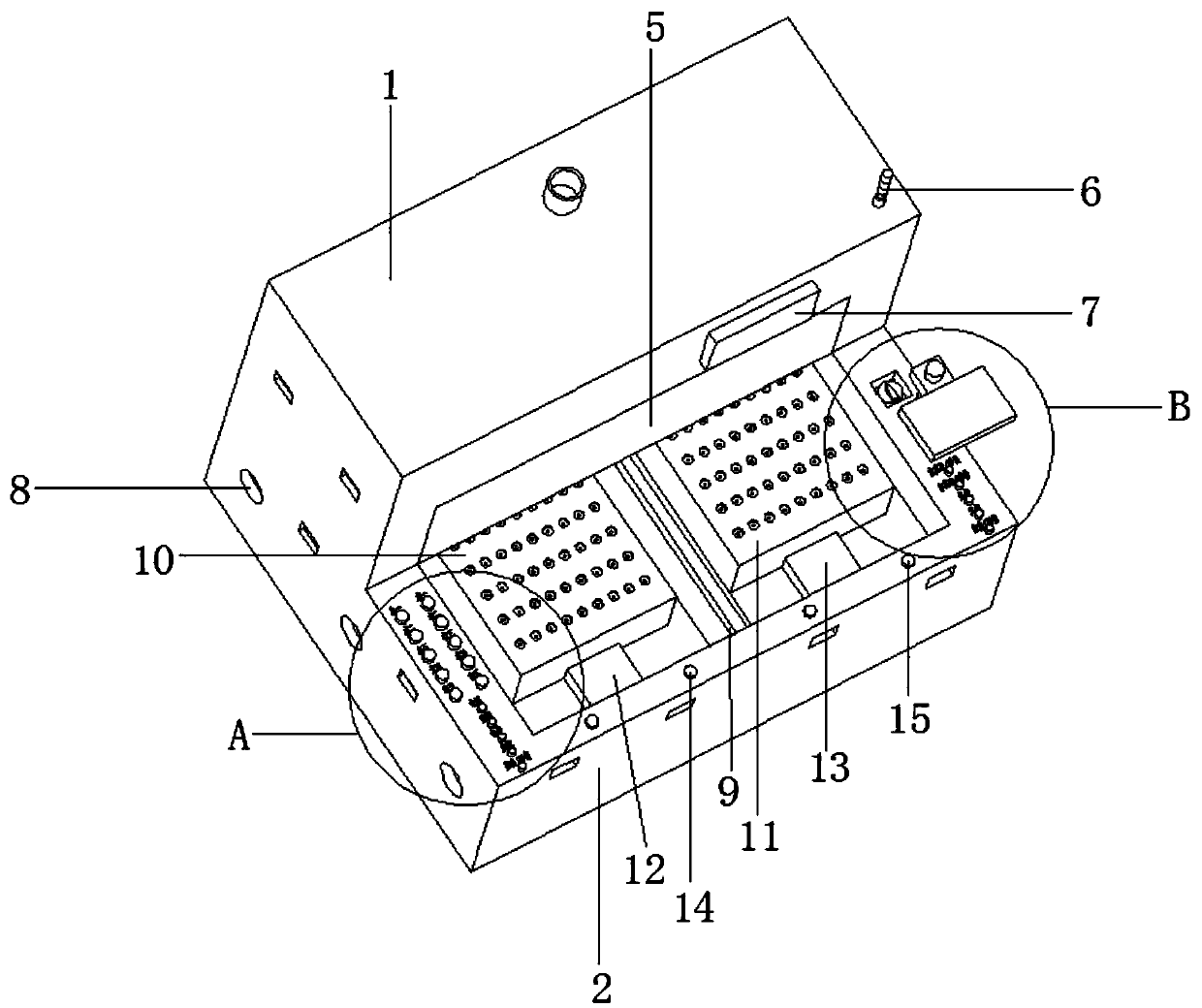
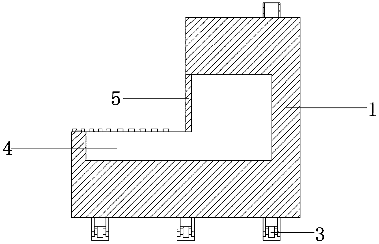
[0033] see Figure 1-7 , the present invention provides a technical solution: an automatic laser marking equipment, including a cabinet 1, the cabinet 1 is L-shaped, the front end of the cabinet 1 is provided with an electric control cabinet 2, and the bottom of the cabinet 1 is provided with a moving wheel 3, There is an L-shaped slot 4 in the center of the top of the cabinet body 1, a laser marking device and a CCD visual positioning system are installed...


PUM


Abstract

The invention discloses an automatic laser marking device in the field of laser marking. Supporting air cylinders and moving wheels are arranged, so that when the supporting air cylinders are retracted, the supporting air cylinders move far away from the ground and the moving wheels make contact with the ground, the automatic laser marking device can be moved by the moving wheels, and when the automatic laser marking device needs to be fixed, an operator can control the supporting air cylinders to stretch so as to enable the height of a horizontal plane where the bottom ends of the supportingair cylinders are located and a horizontal plane where the bottom ends of the moving wheels are located to be the same, so that the bottom ends of the supporting air cylinders and the bottom ends of the moving wheels can make contact with the ground simultaneously for fixing the automatic laser marking device to prevent the automatic laser marking device from moving; by disposing vacuum sucking systems, circular grooves and vacuum sucking holes, a PCB (printed circuit board) can be fixed onto platform plates through vacuum sucking, and therefore the PCB can be fixed quickly and stably; by arranging the platform plates which are respectively a left vacuum platform plate and a right vacuum platform plate, the automatic laser marking device can perform double-station laser marking, so that the marking efficiency is improved.

Description

technical field [0001] The invention relates to the field of laser marking, in particular to an automatic laser marking device. Background technique [0002] Printed circuit board (PCB circuit board), also known as printed circuit board, is the provider of electrical connections for electronic components. Its development has a history of more than 100 years, and its design is mainly layout design; the main advantage of using circuit boards is that it greatly reduces wiring and assembly errors, and improves the automation level and production labor rate. According to the number of layers of circuit boards, it can be divided into single-sided boards, double-sided boards, four-layer boards, six-layer boards and other multi-layer circuit boards. Since the printed circuit board is not a general terminal product, the definition of the name is slightly confusing. They are not the same, so when evaluating the industry, the two are related but cannot be said to be the same. Anothe...

Claims


Application Information

Patent Timeline
IPC IPC(8): B23K26/362B23K26/70
CPCB23K26/362B23K26/70B23K26/702
Inventor 胡锟
Owner 江苏华锟智能科技有限公司
Why Eureka
Try Eureka