
Wheel speed sensor interface control circuit for active electronic brake system

A wheel speed sensor and electronic braking technology, which is applied in the direction of brakes, circuits or fluid pipelines, transportation and packaging, etc., can solve the problems of easy damage of wheel speed sensors, failure of component functions, troublesome replacement and installation, etc., to ensure safety and reliability performance, improve the service life, and protect the circuit

Pending Publication Date: 2019-08-09
思与行科技(苏州)有限公司
View PDF0 Cites 1 Cited by
  • Summary
  • Abstract
  • Description
  • Claims
  • Application Information

AI Technical Summary

Problems solved by technology

[0002] According to the requirements of national laws and regulations, modern cars are basically equipped with ABS (Antilock Brake System, anti-lock braking system) or ESC (Electronic Stability Controller, electronic body stability control system). Both ABS and ESC need to be installed on each wheel of the vehicle. The wheel speed sensor is used to measure the speed of each wheel, and then calculate and control the vehicle; because the wheel speed sensor is exposed outside the car body and installed near the wheel, the working environment is very harsh, especially in rainy and snowy weather, if no effective The protection circuit will cause the wheel speed sensor to be easily damaged; usually each car has at least 4 wheels, that is, the number of wheel speed sensors is generally not less than 4, and one of them is damaged, which will basically cause the ABS / ESC and other components of the car to fail. The function fails, which seriously affects the safety of the vehicle; and the wheel speed sensor belongs to the chassis part of the vehicle, it is troublesome to replace and install, and it needs to be installed and adjusted after replacement

Method used


Image

  • Wheel speed sensor interface control circuit for active electronic brake system
  • Wheel speed sensor interface control circuit for active electronic brake system
  • Wheel speed sensor interface control circuit for active electronic brake system

Examples


Embodiment Construction

[0023] In order to have a further understanding of the purpose, structure, features and functions of the present invention, the detailed description is as follows in conjunction with the embodiments.

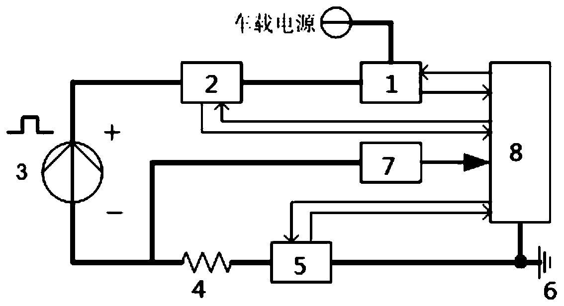
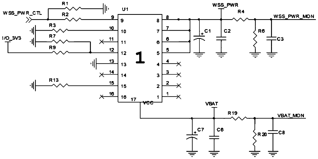
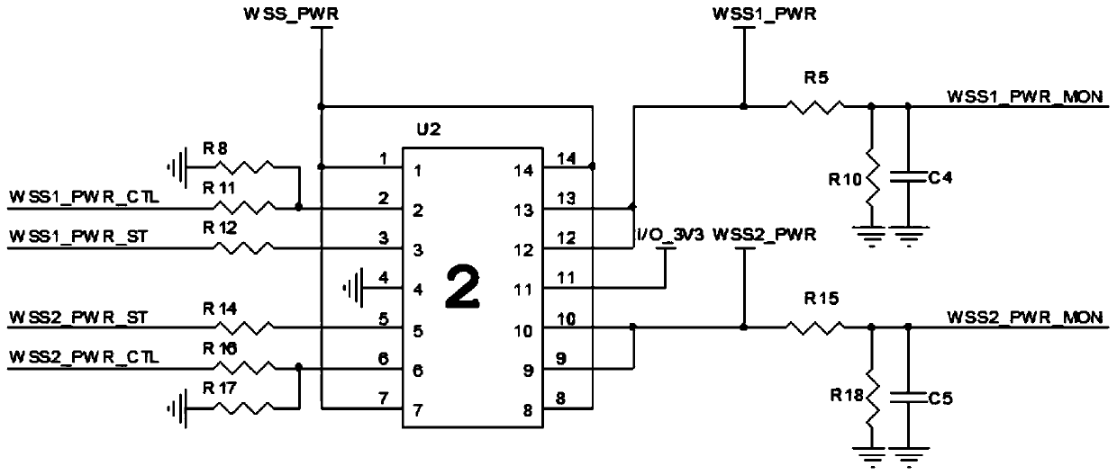
[0024] Such as Figure 1 to Figure 5 As shown, the wheel speed sensor interface control circuit used in the active electronic braking system of the present invention is used in conjunction with the wheel speed sensor 3. The wheel speed sensor 3 includes a positive terminal and a negative terminal, and the wheel speed sensor interface control circuit includes a power switch. Unit 1, high-side power supply unit 2, control unit 8, signal processing unit 7, resistor 4 and low-side power supply unit 5, power switch unit 1 is connected to the vehicle power supply, and high-side power supply unit 2 is respectively connected to the positive pole of the wheel speed sensor 3 The terminal and the power switch unit 1 are electrically connected, the signal processing unit 7 is connected betw...


PUM


Abstract

The invention provides a wheel speed sensor interface control circuit for an active electronic brake system. The wheel speed sensor interface control circuit for the active electronic brake system comprises a power supply switch unit, a high side power supply unit, a control unit, a signal processing unit, a resistor and a low side power supply unit, wherein the power supply switch unit is accessed into a vehicle-mounted power supply; the high side power supply unit is electrically connected with an anode wiring terminal of a wheel speed sensor and the power supply switch unit; the control unit is electrically connected with the power supply switch unit and the high side power supply unit; the signal processing unit is connected between a cathode wiring terminal of the wheel speed sensor and the control unit; the resistor is connected between the cathode wiring terminal of the wheel speed sensor and the low side power supply unit; and the low side power supply unit is further electrically connected with the control unit. According to the wheel speed sensor interface control circuit for the active electronic brake system, the wheel speed sensor can be prevented from working under asevere working environment, the circuit where the wheel speed sensor is arranged is effectively protected, and therefore, the safety and reliability of systems such as ABS and ESC are guaranteed.

Description

technical field [0001] The invention relates to the field of automobiles, in particular to a wheel speed sensor interface control circuit for an active electronic braking system. Background technique [0002] According to the requirements of national laws and regulations, modern cars are basically equipped with ABS (Antilock Brake System, anti-lock braking system) or ESC (Electronic Stability Controller, electronic body stability control system). Both ABS and ESC need to be installed on each wheel of the vehicle. The wheel speed sensor is used to measure the speed of each wheel, and then calculate and control the vehicle; because the wheel speed sensor is exposed outside the car body and installed near the wheel, the working environment is very harsh, especially in rainy and snowy weather, if no effective The protection circuit will cause the wheel speed sensor to be easily damaged; usually each car has at least 4 wheels, that is, the number of wheel speed sensors is general...

Claims


Application Information

Patent Timeline
IPC IPC(8): B60T8/176B60T8/32B60R16/02
CPCB60T8/176B60T8/32B60R16/02
Inventor 姚成华毛靖杨林曹新章
Owner 思与行科技(苏州)有限公司
Learn More