Intelligent padlock

A padlock, intelligent technology, applied in the direction of padlocks, building locks, non-mechanical transmission locks, etc., can solve the problems of inconvenient assembly and production, poor sealing and energy-saving structural design, lack of state detection function, etc., to achieve enhanced anti-corrosion destructive effect

Inactive Publication Date: 2019-08-09
宁波生久科技有限公司
View PDF8 Cites 13 Cited by
  • Summary
  • Abstract
  • Description
  • Claims
  • Application Information

AI Technical Summary

Problems solved by technology

[0003] In order to overcome the above-mentioned shortcomings, the purpose of the present invention is to provide the field with a smart padlock with status monitoring, code scanning and spare interface, so that

Method used


Image

  • Intelligent padlock
  • Intelligent padlock
  • Intelligent padlock

Examples


Embodiment Construction

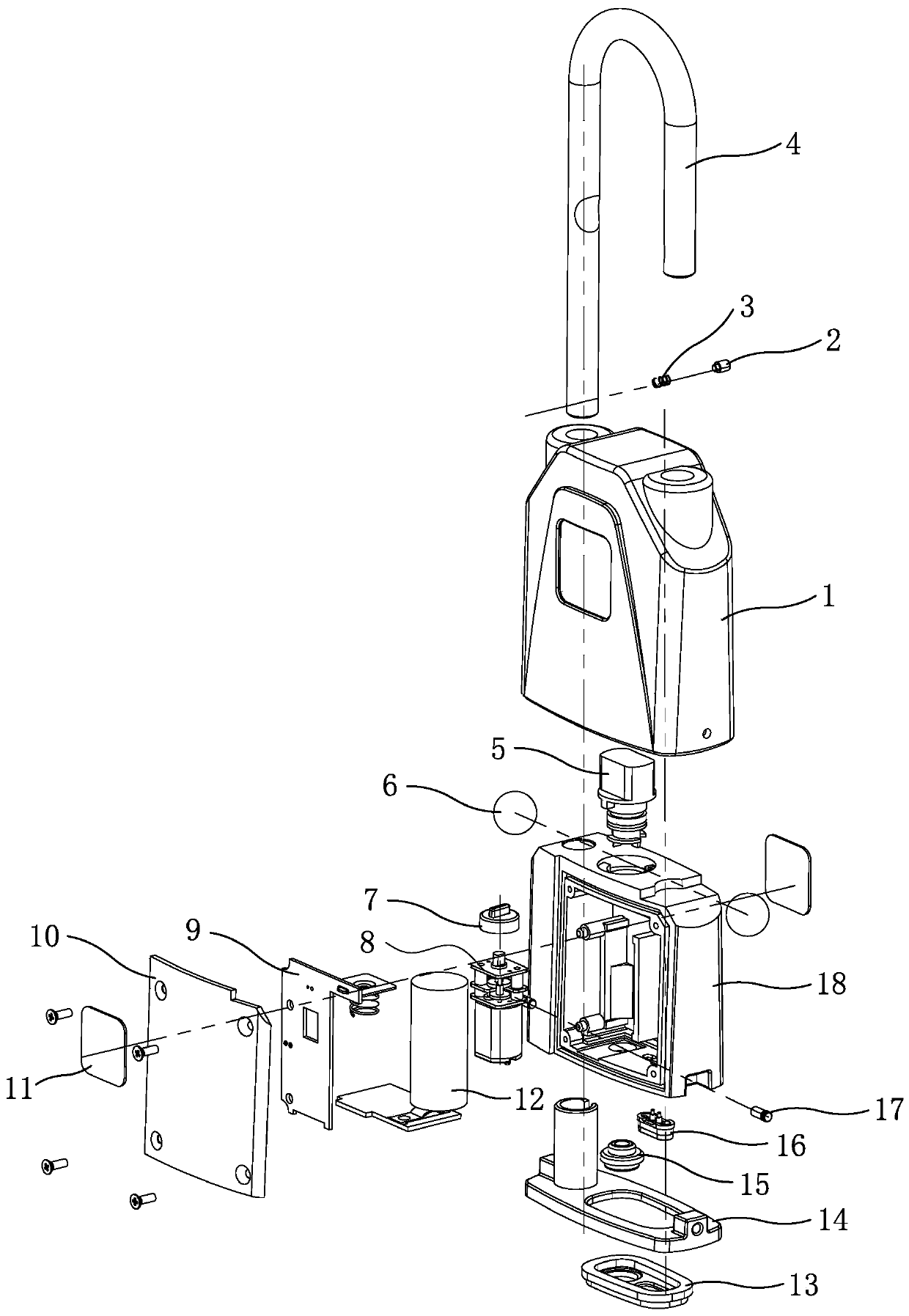
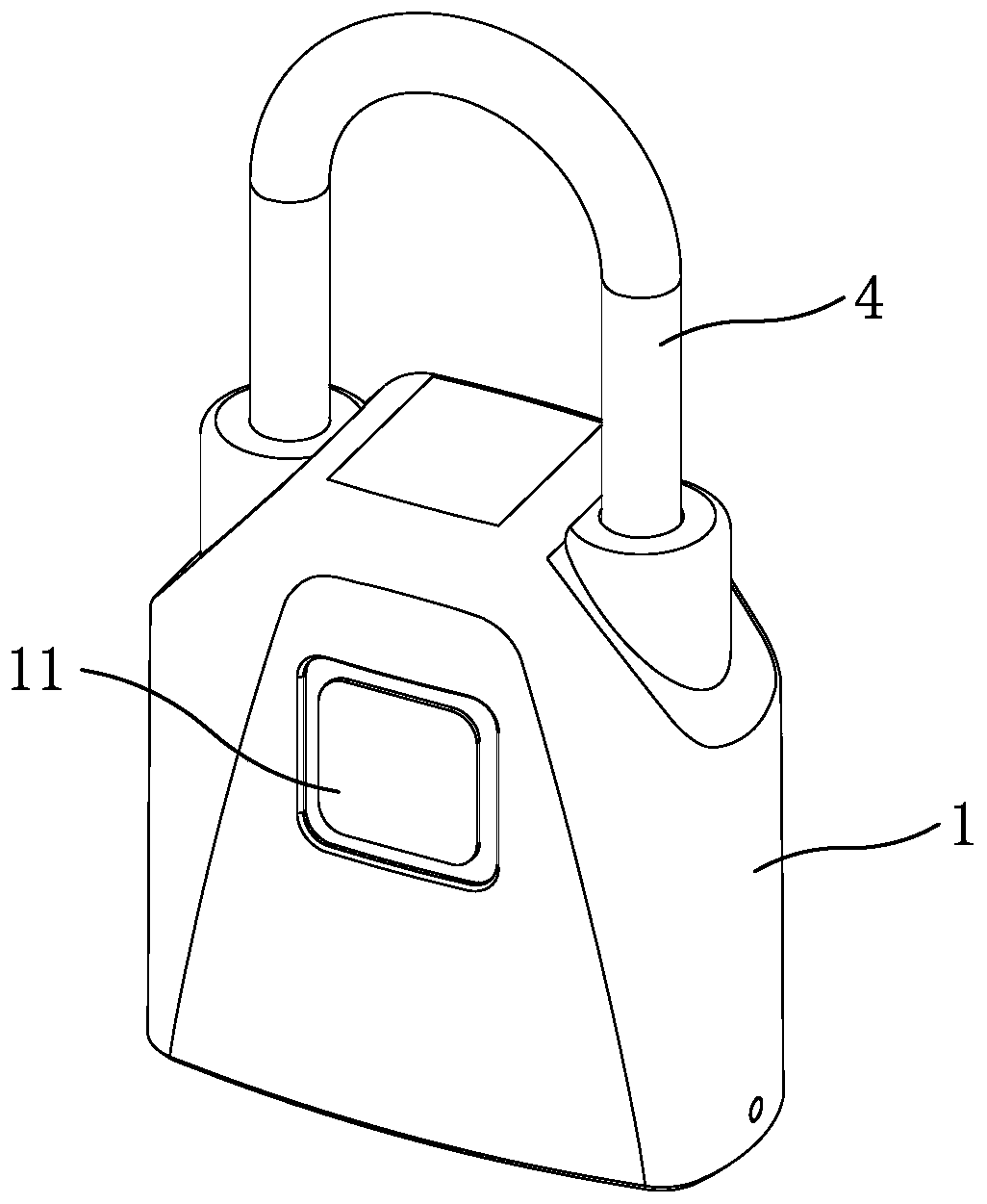
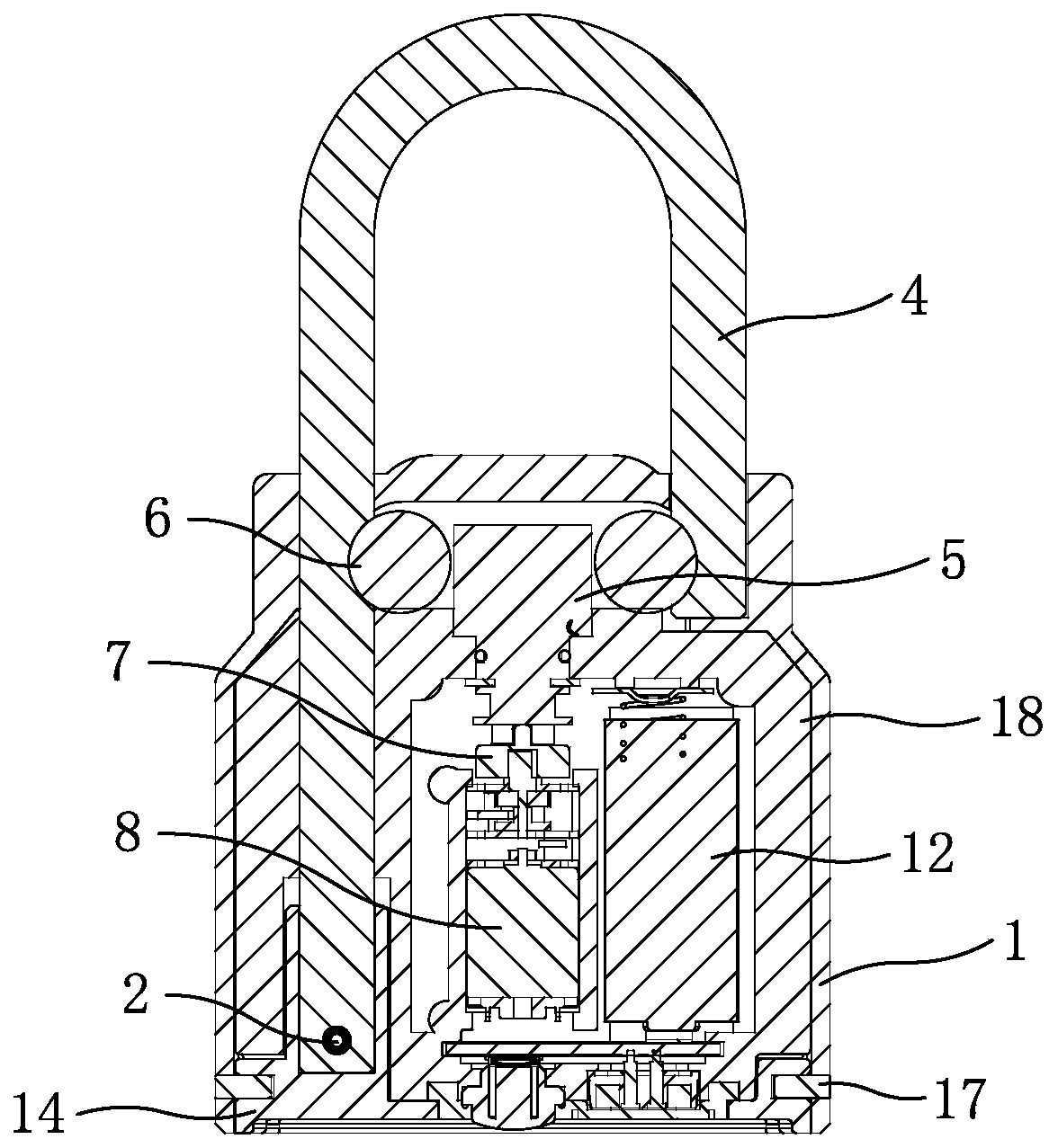
[0022] Now in conjunction with the accompanying drawings, the structure and use of the present invention will be further described. Such as Figure 1-Figure 6 As shown, the lock body 1 of this padlock is provided with a fixed seat 18, and the fixed seat is provided with a lock shaft 5, a motor 8, a circuit board assembly 9, and a battery 12, and the two sides of the lock body are respectively provided with a label 11, and the label is provided with QR code. The steel balls 6 are arranged symmetrically on both sides of one end of the lock shaft. The cylindrical head of the steel ball end of the lock shaft extends out of the shaft hole of the fixing seat. The two sides of the cylindrical head are symmetrically provided with flat key grooves, and the joint between the lock shaft and the fixing seat is provided with a sealing ring. , and the lock ring at the shaft hole of the fixed seat, the lock shaft is fixed on the fixed seat through the lock ring; the steel balls are respecti...


PUM


Abstract

The invention relates to an intelligent padlock, and the intelligent padlock is designed for the technical problems that the existing similar products are inconvenient to assemble and produce, poor insealing performance and energy-saving structural design and lack of a state detection function. A fixing seat is arranged in a lock body of the intelligent padlock; steel balls are symmetrically arranged on the two sides of one end of a lock shaft; the steel balls are respectively locked with lock hook grooves in the inner walls of the two sides of a lock hook in an abutting mode through the lockshaft; and a mobile phone Bluetooth module is arranged on a circuit board assembly. The intelligent padlock is characterized in that one end of a lower cover is provided with a lock hook sleeve; a guide groove is formed in the position, on one side of the lock hook sleeve, of the lower cover; one side of the fixed end of the lock hook is provided with a pin hole; a pin is arranged in the pin holeof the lock hook through a lock hook spring; when the fixed end of the lock hook is sleeved with the lock body and fixed on the fixing seat, the pin extends out of the guide groove of the lower coverby abutting against the lock hook spring; the lock hook is limited on a gap ring groove above the lock hook sleeve of the lower cover in the fixing seat through the pin; the gap ring groove is a rotating groove; a lock shaft spring is arranged between a limiting rib of the lock shaft and a limiting groove of the fixing seat; and a photoelectric switch is arranged at a gap of the lock shaft.

Description

technical field [0001] The invention relates to a padlock, which is an intelligent padlock. Background technique [0002] A padlock is a lock with a ring-shaped or in-line lock beam that can be buckled on the lock body. It is directly buckled with the lock body through the lock beam to form a closed lock. At present, the more common padlock structure is a padlock with a tumbler structure, that is, when the key is inserted into the key slot of the lock cylinder, the lock beam can be pulled upward without rotation. With the development of science and technology, some existing padlocks combine fingerprint unlocking technology, and lock the shackle through a double steel ball structure; such as the application number 201810480681.4 disclosed in the Chinese patent literature, the application publication date is 2018.08.31, and the invention name is "a fingerprint Padlock"; the padlock includes: a controller, a fingerprint collection module, a locking mechanism, an electronic loc...

Claims


Application Information

Patent Timeline
IPC IPC(8): E05B67/22E05B47/00E05B67/38E05B15/00E05B15/14G07C9/00
CPCE05B15/14E05B47/0001E05B47/0012E05B67/22E05B67/38E05B2047/0024E05B2047/0058G07C9/00182
Inventor 姚春良徐良坤张晓宇
Owner 宁波生久科技有限公司
Why Eureka
Try Eureka