Powerful cam brake balancing device

A balancing device and cam technology, which is applied in the field of vehicle parts, can solve the problems of the inner wall of the brake drum, the wear of the inner wall of the brake drum, and the impact on driving safety, etc., and achieve the advantages of increased contact area, large braking force, and improved stability Effect

Pending Publication Date: 2019-08-09
广西环江航舵汽车科技有限公司
View PDF0 Cites 0 Cited by
  • Summary
  • Abstract
  • Description
  • Claims
  • Application Information

AI Technical Summary

Problems solved by technology

[0003] The shape of the brake shoe is like a half-moon. When the brake is stepped on, the two half-moon-shaped brake shoes are stretched out under the action of the brake wheel cylinder, and the brake shoes are propped up to rub against the inner wall of the brake drum to slow down or stop. During the braking process of the brake shoe, whether it is slow braking or emergency braking, the inner wall of the brake drum will be worn; after a long period of wear, the inner wall of the brake drum will be dented; the braking effect will gradually decrease, affecting people's driving Safety

Method used


Image

  • Powerful cam brake balancing device
  • Powerful cam brake balancing device
  • Powerful cam brake balancing device

Examples


Embodiment Construction

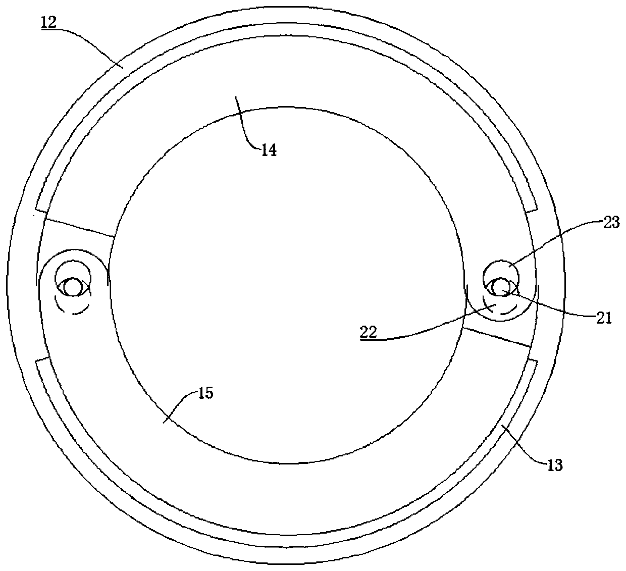
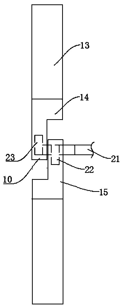
[0026] The invention discloses a powerful cam brake balance device, comprising a brake drum, a bottom plate 12, a friction plate 13, a left brake shoe 14, a right brake shoe 15 and a cam mechanism, the left brake shoe 14 and the right brake shoe 15 There are docking blocks 10 respectively at both ends of the docking block 10, cam holes are provided on the docking block 10, the left brake shoe 14 and the right brake shoe 15 are installed on the bottom plate 12 and are located in the brake drum, the left brake shoe 14 and the right brake shoe The movable shoes 15 are respectively slidingly connected with the bottom plate 12 through the sliding block structure of the chute, and the left brake shoe 14 and the right brake shoe 15 are arranged oppositely to form two pairs of opposite ends, and the docking blocks 10 on each pair of opposite ends are arranged staggered inside and outside , in the present embodiment, the butt blocks 10 at both ends of the left brake shoe 14 are arranged...


PUM


Abstract

The invention provides a powerful cam brake balancing device. The powerful cam brake balancing device comprises a brake drum, a bottom plate, friction plates, a left brake shoe, a right brake shoe andcam mechanisms, wherein the two ends of the left brake shoe and the right brake shoe are separately provided with butt blocks; the butt blocks are provided with cam holes; the left brake shoe is opposite to the right brake shoe to form two pairs of opposite ends; the butt blocks on each pair of opposite ends are arranged in an inner and outer staggered mode; each cam mechanism is arranged betweeneach pair of opposite ends; each cam mechanism comprises a camshaft, an inner cam and an outer cam, wherein the inner cam and the outer cam are separately fixed on the camshaft; the outer cams are eccentrically arranged relative to the inner cams; the outer cams are arranged in cam holes of the outer butt blocks; and the inner cams are arranged in the cam holes of the inner butt blocks. By meansof the powerful cam brake balancing device, the technical problems of low braking force and insensitive braking can be solved.

Description

technical field [0001] The invention relates to the technical field of vehicle parts, in particular to a powerful cam brake balancing device. Background technique [0002] Drum brakes generally adopt drum brakes. Drum brakes are composed of rotating parts and fixed parts, including brake bottom plates, brake wheel cylinders, brake shoes, etc. Drum brakes have a cast iron piece similar to a tambourine, called a brake. The drum, which is fixed to the tire and turns at the same speed. Drum brakes have lower cost and higher absolute braking force, and are more widely used on the rear wheels of vehicles. But its wear rate is high, so the overall cost is high at the same time. The brake shoe refers to the accessories that are pushed outward by the force of the brake wheel cylinder or push rod to suppress the brake drum to perform the braking effect. It is installed on the brake drum. It is one of the key safety parts in the automobile braking system. [0003] The shape of the b...

Claims


Application Information

Patent Timeline
IPC IPC(8): F16D51/22F16D65/18B60T1/06B60T13/24B60T17/10F16D121/14F16D125/28
CPCF16D51/22F16D65/18B60T13/24B60T17/10B60T1/067F16D2121/14F16D2125/28
Inventor 梁芳文
Owner 广西环江航舵汽车科技有限公司
Why Eureka
Try Eureka