Speed reducer

A technology of reducer and casing, applied in the direction of transmission parts, components with teeth, belt/chain/gear, etc., can solve the problems of large shaking of the reducer, loud noise of the reducer, etc., to avoid noise and strengthen the seal. effect, long service life effect

Active Publication Date: 2019-08-09
青岛海力达齿轮箱有限公司
View PDF6 Cites 0 Cited by
  • Summary
  • Abstract
  • Description
  • Claims
  • Application Information

AI Technical Summary

Problems solved by technology

However, since the fan is connected to the output shaft of the reducer, the rotation of the fan will drive the reducer to shake a lot during operation, which will cause the reducer to shake relative to the grid and generate a lot of noise

Method used


Image

  • Speed reducer
  • Speed reducer
  • Speed reducer

Examples


Embodiment Construction

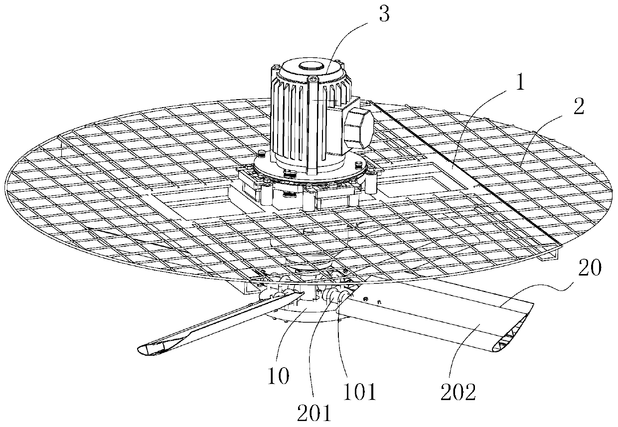
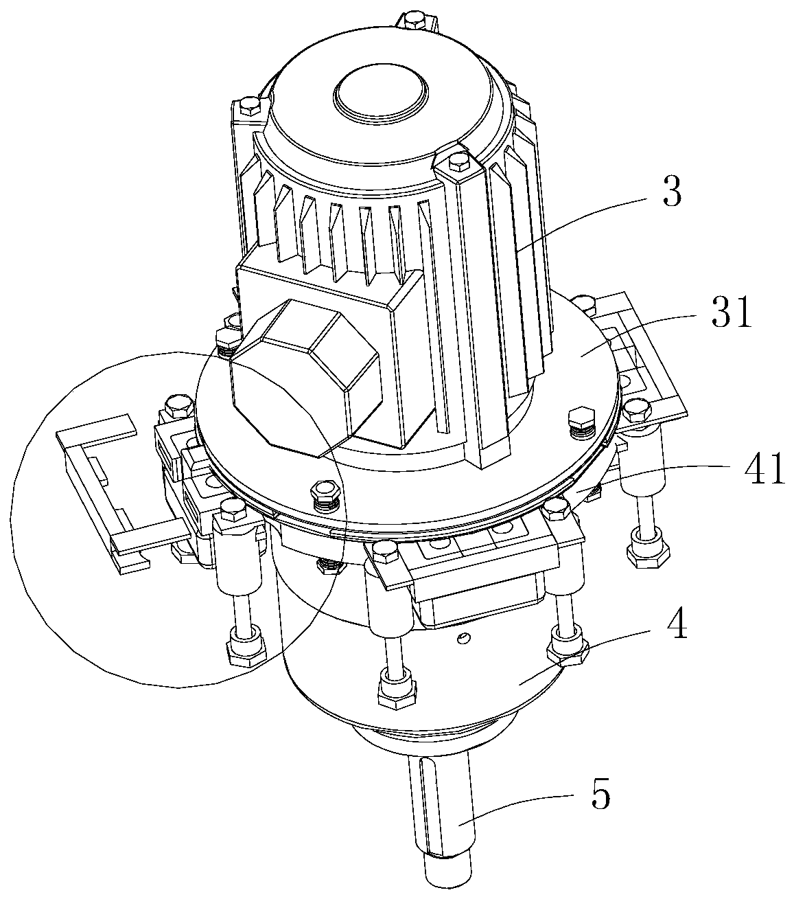
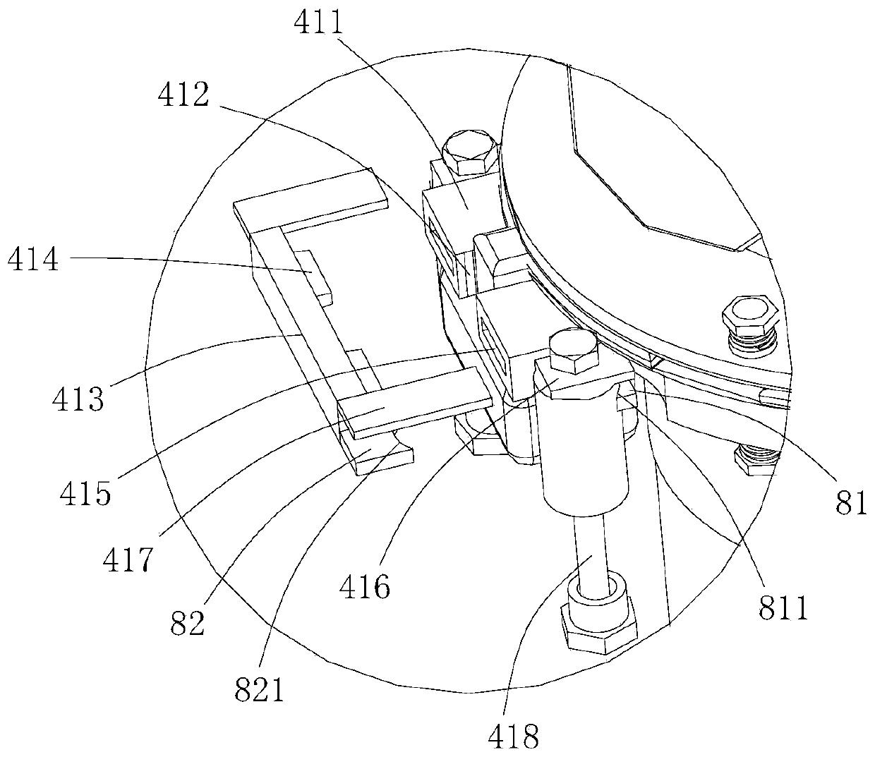
[0029] Such as Figure 1-9 As shown, a reducer is arranged on a cooling tower, and the output shaft of the reducer is connected with a fan. The upper part of the cooling tower is provided with a support 1 and a wire mesh 2, and the reducer is arranged on the support 1 ; Including the upper casing 3 and the lower casing 4; the output shaft 5 is arranged on the lower casing 4; the connecting device is used to limit and fix the reducer to the support frame 1; the shock-absorbing seal 6 has a sealing part 61. A shock-absorbing portion 62 and a connecting portion 63 for connecting the shock-absorbing portion and the sealing portion. The sealing portion 61 is placed at the connection of the upper and lower casings, and the upper and lower surfaces are respectively sealed and matched with the upper and lower casings; the shock-absorbing portion 62 is provided between the lower casing 4 and the support frame 1, and is used to realize the shock absorption operation of the reducer; the i...


PUM


Abstract

The invention discloses a speed reducer which is arranged on a cooling tower. An output shaft of the speed reducer is connected with a fan; a support frame and a mesh are arranged on the upper part ofthe cooling tower; the speed reducer is arranged on the support frame and comprises an upper case, a lower case, an output shaft, a connecting device and a shock absorption sealing piece; the outputshaft is arranged on the lower case; the connecting device is used for limiting and fixing the speed reducer onto the support frame; the shock absorption sealing piece is provided with a sealing part,a shock absorption part and a connecting part for connecting the shock absorption part and the sealing part; the sealing part is arranged on the connecting part of the upper case and the lower case;the upper surface and the lower surface are in seal fit with the upper case and the lower case; and the shock absorption part is arranged between the lower case and the support frame and is used for realizing the shock absorption operation on the speed reducer. According to the speed reducer provided by the invention, the shock absorption of the speed reducer can be realized, the generation of noise is avoided when the speed reducer works, meanwhile, a sealing effect of the connecting part of the upper case and the lower case is improved, no leakage happens after long-time use, and the servicelife is long.

Description

Technical field [0001] The invention belongs to the technical field of reducers, and in particular relates to a reducer. Background technique [0002] The current cooling tower reducer is usually a combined assembly structure, and the upper and lower shells are connected to each other by a structure such as screws. However, the sealing of the connection between the upper and lower shells has always been a long-term problem. After long-term use, the sealing performance is prone to failure, causing the reducer to leak. The internal lubricating oil is gradually reduced, and the external water will enter the lubrication chamber, which will seriously affect the reducer. Life. [0003] And when the reducer is connected to the cooling tower, the usual way is to connect the reducer shell to the grid on the upper part of the cooling tower by screws. However, due to the fan connected to the output shaft of the reducer, the rotation of the fan will drive the reducer to shake a lot during op...

Claims


Application Information

Patent Timeline
Patent Type & Authority Applications(China)
IPC IPC(8): F16H57/025F16H57/028F16H57/029F16H57/02
CPCF16H57/025F16H57/028F16H57/029F16H57/02F16H2057/02069F16H2057/02021
Inventor 陈小标陈玉飞谢百锋陈杰
Owner 青岛海力达齿轮箱有限公司
Why Eureka
Try Eureka