Cloth drying device used for textile processing

A technology for drying fabrics and textiles, applied in textiles and papermaking, drying, dryers, etc., can solve the problems of breeding bacteria, affecting the normal use requirements of textile processing, and easy wrinkling or folding of fabrics, so as to improve efficiency. Effect

Active Publication Date: 2019-08-09
ANHUI SWAN TECH IND GRP
View PDF8 Cites 7 Cited by
  • Summary
  • Abstract
  • Description
  • Claims
  • Application Information

AI Technical Summary

Problems solved by technology

[0004] The object of the present invention is to provide a cloth drying device for textile processing to solve the complicated drying and winding process proposed in the above background technology and the situation that the cloth is prone to wrinkles or folds during the drying process. As a result, the drying efficiency of the cloth is not high. Once it is rolled up and stacked together, bacteria will breed, which will affect the normal use requirements of textile processing.

Method used


Image

  • Cloth drying device used for textile processing
  • Cloth drying device used for textile processing
  • Cloth drying device used for textile processing

Examples


Embodiment 1

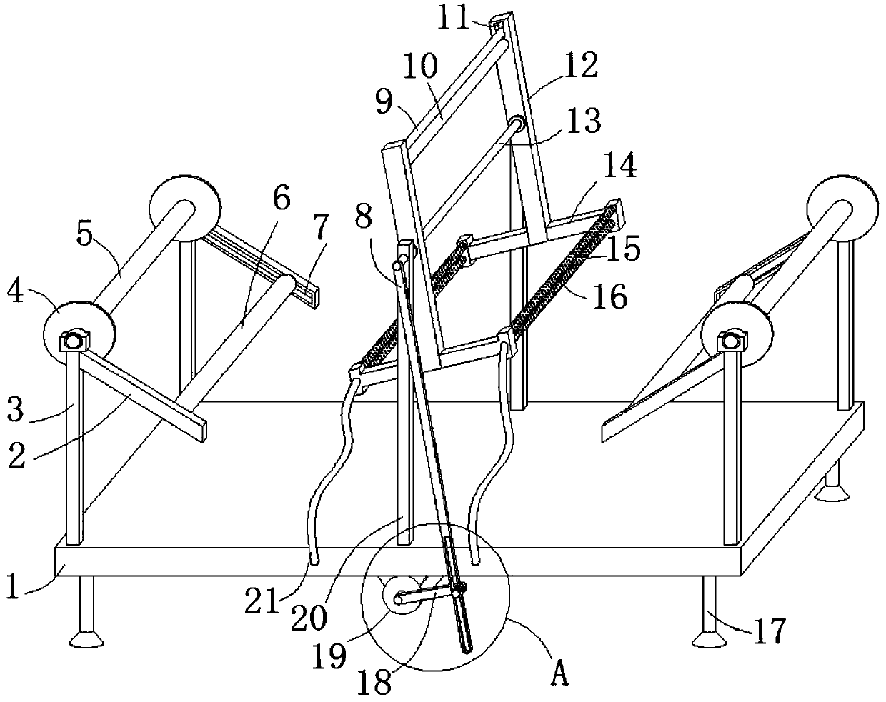
[0024] see Figure 1-4 , the present embodiment provides a cloth drying device for textile processing, including a base 1, the left and right sides of the top surface of the base 1 are vertically welded with front and back symmetrical support columns 3, and the tops of the left two support columns 3 and the The tops of the two support columns 3 on the right are rotated and plugged with guide rollers 5, the top right sides of the two support columns 3 on the left side and the top left sides of the two support columns 3 on the right are all inclined downward and welded with guide rods 2. The opposite side walls of the two guide rods 2 on the left side and the opposite side walls of the right guide rod 2 are provided with chute 7, and the weight roller 6 is slidingly clamped through the chute 7, and the front and rear sides of the middle section of the top surface of the base 1 A support rod 20 is vertically welded, and a transmission roller 13 is inserted and rotated between the...

Embodiment 2

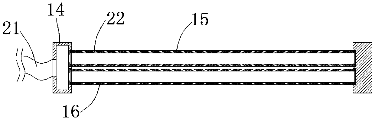
[0028] see Figure 1-4On the basis of Embodiment 1, a further improvement is made: the angle between the guide rod 2 and the horizontal plane is 45 degrees, which facilitates the guide roller 5 to slide in the inner cavity of the chute 7 to achieve the purpose of tensioning the cloth. The inner cavity length of the waist-shaped hole 24 is equal to 2.2 times of the length of the connecting rod 18, which is convenient for the connecting rod 18 to do circular motion, thereby driving the purpose of the hinged rod 8 to swing left and right. Vertically distributed lifting grooves 11, and between the two lifting grooves 11, there is a counterweight roller 9 that can slide up and down in the cavity of the lifting groove 11. The weight roller 9 is located above the ironing column 10. By setting the weight roller 9. It is convenient to tightly fit the cloth to the ironing column 10, and achieve a good ironing and drying effect. The air outlets 22 of the first air supply cylinder 15 and ...


PUM


Abstract

The invention discloses a cloth drying device used for textile processing. The cloth drying device comprises a base; opposite side walls of two guiding rods on the left side and opposite side walls oftwo guiding rods on the right sides are separately provided with slide chutes; weight rollers are slidably clamped through the slide chutes; an ironing post is fixedly arranged between the top ends of a front supporting plate and a rear supporting plate; a first air supplying barrel and a second air supplying barrel which are vertically arrayed are rotatably inserted between the ends, which are far away from the supporting plates of two T-shaped blocks on the left side; a first air supplying barrel and a second air supplying barrel which are vertically arrayed are rotatably inserted between the ends, which are far away from the supporting plates of two T-shaped blocks on the right side; besides, the first air supplying barrels and the second air supplying barrels communicate with cavitiesin the ends, which are far away from the supporting plates, of the two T-shaped blocks on the front side; a hot air blower is embedded in the cavity in the base; and a plurality of oblique air blowing openings are formed in the outer walls of the first air supplying barrel and the second air supplying barrel. By adopting the cloth drying device, textile cloths can be rapidly dried; besides, the phenomena of cloth wrinkling and folding cannot happen; high-efficient and reliable drying operation is ensured; and textile processing efficiency is improved.

Description

technical field [0001] The invention relates to the technical field related to textile processing and production, in particular to a cloth drying device for textile processing. Background technique [0002] Textiles are products made of textile fibers through processing and weaving. They are divided into two categories: woven fabrics and knitted fabrics. China is one of the earliest countries in the world to produce textiles. In weaving, it is necessary to dry and roll the cloth. Rolling and stacking the cloth can increase the accumulation of the cloth and make the cloth look more tidy. [0003] At present, the cloth is first dried by a dryer, and then rolled up for stacking, which requires a lot of manpower and material resources to dry and arrange the cloth, and then rolls the cloth with a cloth rolling device, so that It takes more time to produce the fabric, which leads to a slower production speed of the fabric. In addition, during the drying process, the fabric is pro...

Claims


Application Information

Patent Timeline
Patent Type & Authority Applications(China)
IPC IPC(8): F26B13/14F26B21/00D06C15/02
CPCD06C15/02F26B13/145F26B21/004
Inventor 储荣生
Owner ANHUI SWAN TECH IND GRP
Why Eureka
Try Eureka