
Charge pump, control method and chip

A charge pump and signal control technology, which is used in automatic power control, electrical components, and conversion equipment without intermediate conversion to AC. It can solve the problem of small phase-locked loop jitter, and the inability of the charge pump to take into account the locking speed and output voltage stability. The output voltage Vout has a small change speed and other problems, so as to ensure the output stability and solve the problem that the locking speed and output stability cannot be balanced.

Active Publication Date: 2019-08-09
HUNAN GOKE MICROELECTRONICS
View PDF5 Cites 2 Cited by
  • Summary
  • Abstract
  • Description
  • Claims
  • Application Information

AI Technical Summary

Problems solved by technology

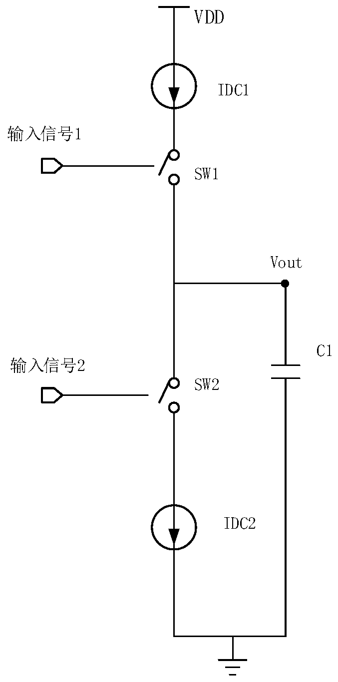
[0004] When this charge pump is used in a phase-locked loop circuit, Vout is the voltage-controlled oscillator control voltage of the phase-locked loop circuit. When the phase-locked loop is locked with a larger C1, the output voltage Vout is more stable, so that the phase-locked loop The jitter is smaller, but at the same time, the change speed of the output voltage Vout is smaller, and the locking time of the phase-locked loop increases, thereby reducing the overall performance of the system where the phase-locked loop is located. Therefore, in the prior art, the charge pump cannot balance the locking speed and the output after locking voltage stability

Method used


Image

  • Charge pump, control method and chip
  • Charge pump, control method and chip
  • Charge pump, control method and chip

Examples


Embodiment Construction

[0041] The following will clearly and completely describe the technical solutions in the embodiments of the present invention with reference to the accompanying drawings in the embodiments of the present invention. Obviously, the described embodiments are only some, not all, embodiments of the present invention. Based on the embodiments of the present invention, all other embodiments obtained by persons of ordinary skill in the art without making creative efforts belong to the protection scope of the present invention.

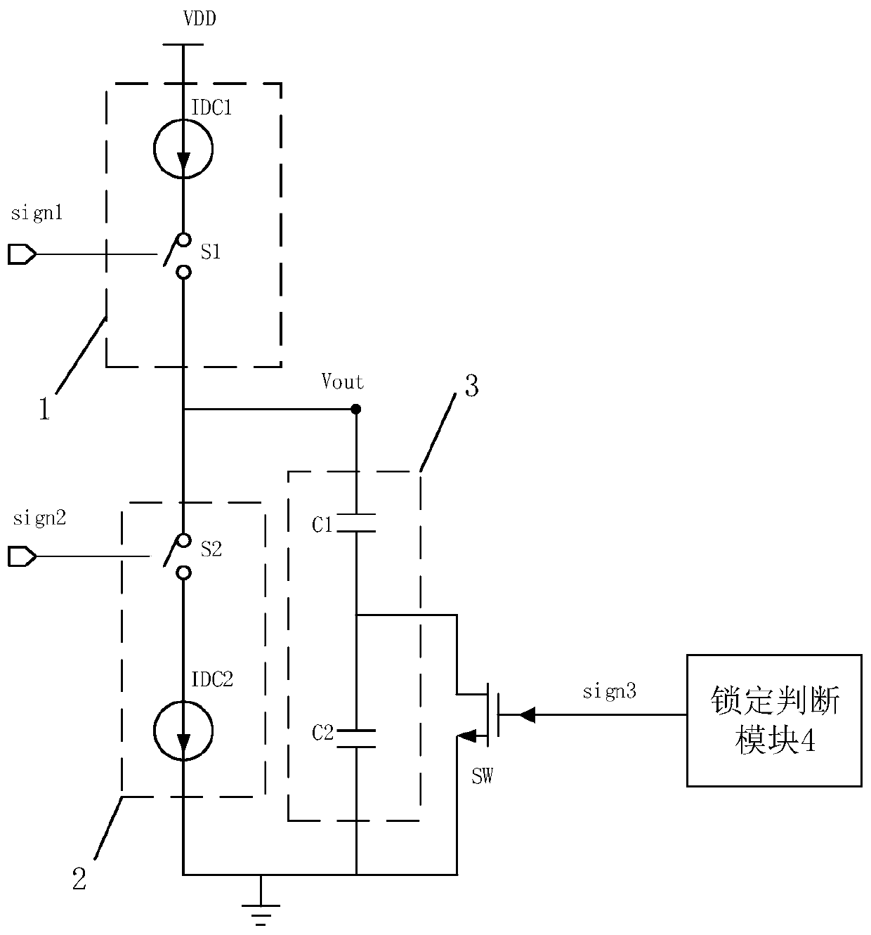
[0042] The charge pump in the prior art can make the output voltage more stable when using a larger capacitor, and can increase the locking speed when using a smaller capacitor, but because the capacitor of the charge pump in the prior art is fixed, the equivalent capacitance Therefore, it is impossible to balance the locking speed and the stability of the output voltage after locking.

[0043] In the present invention, two capacitor units are connected in ser...


PUM


Abstract

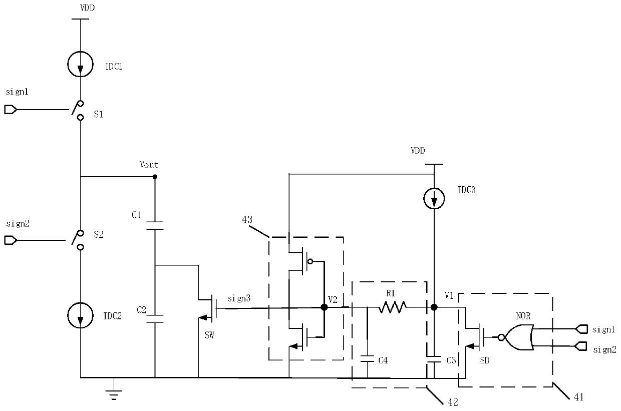
The invention discloses a charge pump, a control method and a chip. The charge pump comprises a first power module, wherein the first end of the first power module is connected with a preset power supply, the second end of the first power module serves as a voltage output end and is controlled by a first signal; a second power module, wherein the first end of the second power module is connected with the voltage output end, the second end of the second power module is grounded, and the second power module is controlled by a second signal; a capacitor module which is in parallel connection withthe second power module; a locking judgment module and a state switch. The capacitor module comprises a first capacitor unit and a second capacitor unit which are connected in series, and the state switch is in parallel connection with the second capacitor unit. The locking judgment module outputs a judgment signal for controlling the state switch according to the first signal and the second signal. When it is judged that the signal controls the state switch to be switched off, the first capacitor unit and the second capacitor unit which are connected in series are connected into a current loop, the equivalent capacitance is smaller, and the voltage of the voltage output end changes fast; when the judgment signal controls the state switch to be switched on, only the first capacitor unit is connected into the current loop, and meanwhile, the output stability of the voltage of the voltage output end is guaranteed.

Description

technical field [0001] The invention relates to the field of analog integrated circuits, in particular to a charge pump, a control method and a chip. Background technique [0002] As a functional circuit module in analog integrated circuits, the charge pump is mainly used in phase-locked loops and digital-to-analog / analog-to-digital conversion circuits. One of its main functions is to convert pulse signals into voltage signals. Prior art charge pump circuits such as figure 1 As shown, it can convert the pulse of input signal 1 or input signal 2 into voltage Vout output. [0003] exist figure 1 Among them, switches SW1 and SW2 are controlled by input signal 1 and input signal 2 respectively. In a phase-locked loop circuit, usually only one of the input signal 1 and the input signal 2 is a high-level pulse, and the signal of the high-level pulse controls the corresponding switch to turn on, forming a loop between the corresponding current source and the capacitor, and the c...

Claims


Application Information

Patent Timeline
Patent Type & Authority Applications(China)
IPC IPC(8): H02M3/07H03L7/085
CPCH02M3/07H03L7/085
Inventor 何力
Owner HUNAN GOKE MICROELECTRONICS
Learn More