System and method for programming and/or management of core network slices

A network slicing and management system technology, applied in the field of programming and/or managing mobile wireless networks, can solve problems such as low efficiency, and achieve the effect of preventing network errors, preventing damage, and preventing resource allocation problems

Active Publication Date: 2019-08-09
HUAWEI TECH CO LTD
7 Cites 1 Cited by

AI-Extracted Technical Summary

Problems solved by technology

However, the scalability of mobil...

Abstract

There is provided, a network slice programming and management system for slicing a network to multiple groups of logical network slices composed of a collection of logical network functions, each dedicated to supporting a specific respective use for subscribers of the slice, comprising of a programming interface configured to receive commands for creation and/or configuration of network slice design comprising the constraints and requirements defining an architecture of logical network functions that when deployed form a network slice of a network, the commands include selection of at least one network function and a definition of an interaction of the selected at least one network function with other network functions.

Application Domain

Assess restrictionMultiprogramming arrangements +3

Technology Topic

Management systemCore network +1

Image

  • System and method for programming and/or management of core network slices
  • System and method for programming and/or management of core network slices
  • System and method for programming and/or management of core network slices

Examples

  • Experimental program(1)

Example Embodiment

[0041] The present invention relates to network management in some of its embodiments, and more specifically but not exclusively, to systems and methods for programming and/or managing mobile wireless networks.
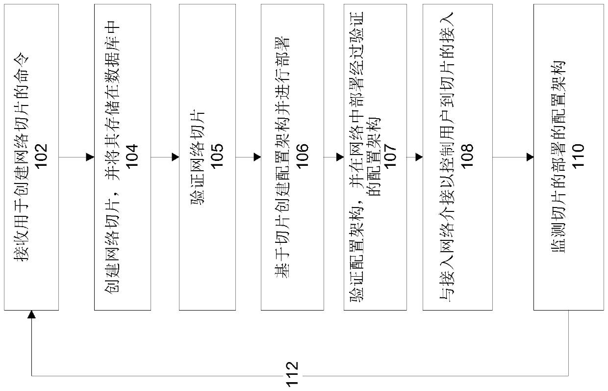
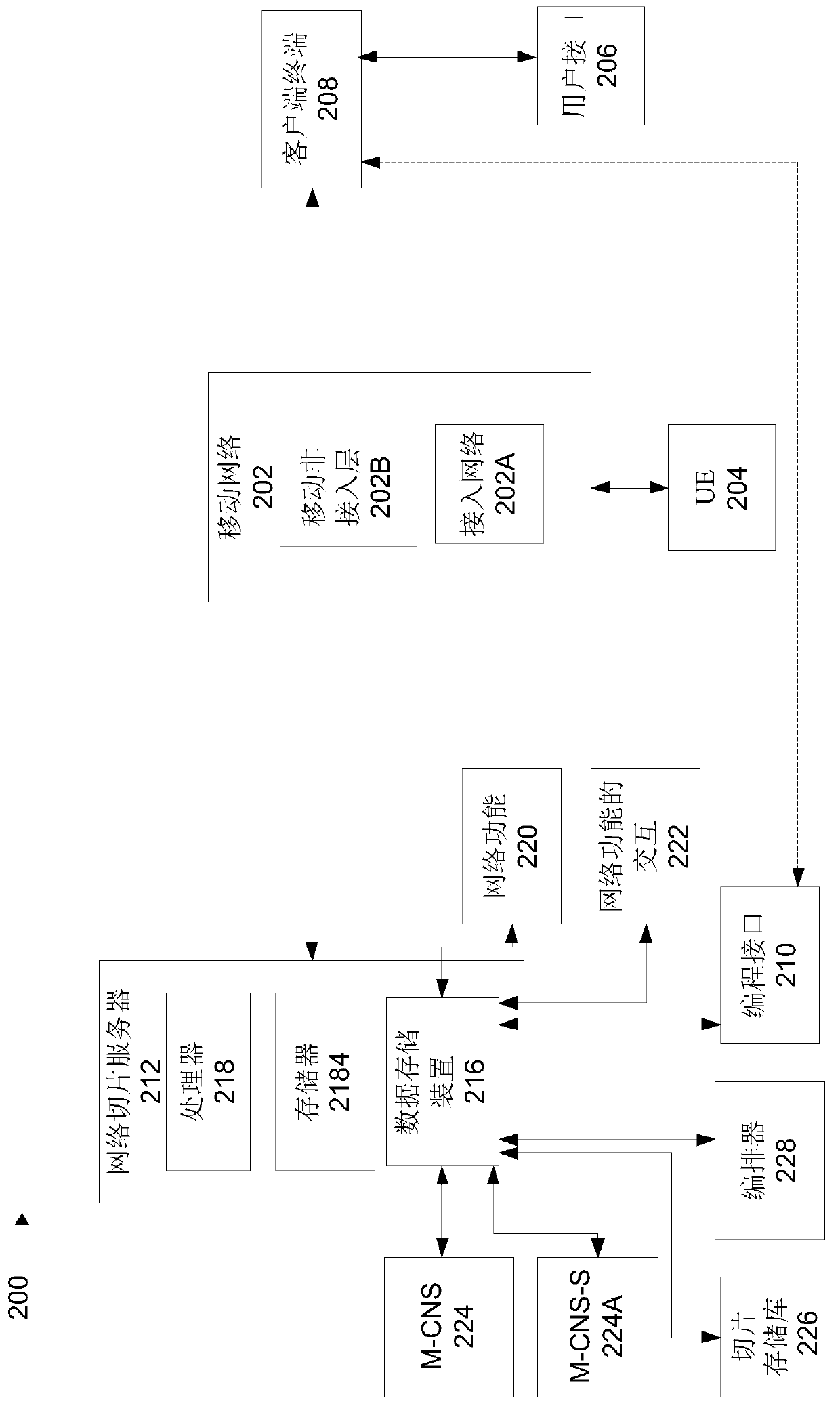
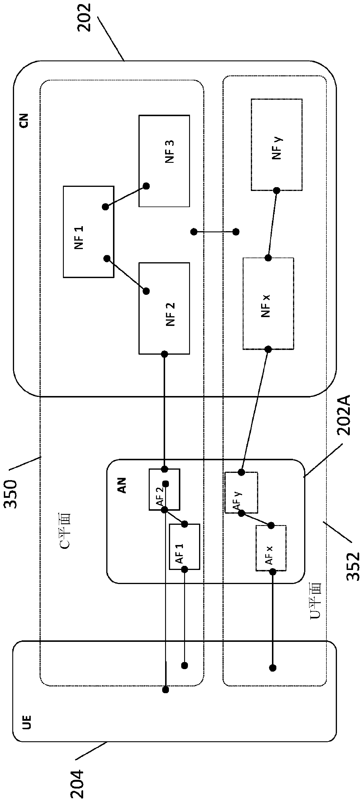
[0042] An aspect of some embodiments of the present invention relates to a device (for example, a network slicing server), a system (also referred to herein as a network slice programming and management system), and a method (for example, implemented as stored in a storage Code instructions executed by one or more processors in the device), and/or a computer program product, which defines slices of a mobile communication network as multiple sets of logical network slices. Each network slice is associated with a set of logical network functions, which are optionally virtualized network functions. Each network function is dedicated to supporting specific corresponding use for sliced ​​users. The sliced ​​network function defines an architecture for a specific purpose, for example, devices and/or applications, for example, real-time communication, high-reliability communication, and/or high-bandwidth communication. A configuration architecture based on the requirements of the network slice and the network slice creator (eg, user, requesting entity) is created and deployed in the mobile network.
[0043] The definition of slice is to use programming interface (for example, application programming interface (application programming interface, API), software development kit (software development kit, SDK), graphical user interface (graphical user interface, GUI)) to perform, programming interface to receive Commands for creating and/or configuring the corresponding network slice design. The network slicing is additionally associated with constraints and/or requirements that define the configuration architecture of the logical network function, and the configuration architecture of the logical network function forms a corresponding network slice of the mobile wireless network when deployed. Exemplary commands include the selection of network functions, and the definition of the interaction of the selected network functions with other network functions.
[0044] System (also referred to herein as a network slicing programming and management system), method (e.g., implemented as code instructions stored in a storage device and executed by one or more processors), apparatus, and/or the computer described herein The program product defines a programming interface that can be used in the control plane of a modular mobile network, such as the 5th generation mobile technology (5G) and higher. The operator of the mobile network and/or the client of the mobile network uses a programming interface to define a customized slice in the mobile network based on predefined and/or customized network functions. This slice can then be deployed by the orchestration component.
[0045] The system (also referred to herein as a network slicing programming and management system), method (for example, implemented as code instructions stored in a storage device and executed by one or more processors), apparatus, and/or as described herein The computer program product provides a programming interface, and the programming interface is used to create logical network slices that support different usage conditions. The logical network slices may differ in performance attributes and/or other requirements. Compared with the common adjustment common architecture in existing mobile networks (for example, one architecture is suitable for all solutions), slices are defined for different devices and/or applications according to the corresponding different requirements of the devices and/or applications. Each device and/or application is associated with a network slice, and the network slice is configured according to the customization requirements of the device and/or application. For example, one type of slice can define ultra-reliable communication for critical services such as e-health care, public safety, real-time vehicle control, perception of the Internet, drone connections, and so on. Another type of slicing can define communications that are not necessarily required to provide high reliability and/or real-time response.
[0046] Before explaining at least one embodiment of the present invention in detail, it should be understood that the present invention in its application is not necessarily limited to the construction of the components and/or methods set forth in the following description and/or illustrated in the drawings and/or examples And the details of the layout. The present invention can have other embodiments or be practiced or carried out in various ways.
[0047] The present invention can be a system, a method and/or a computer program product. The computer program product may include one or more computer-readable storage media having computer-readable program instructions thereon to cause a processor to perform various aspects of the present invention.
[0048] The computer-readable storage medium may be a tangible device capable of holding and storing instructions for use by the instruction execution device. The computer-readable storage medium may be, for example, but not limited to: an electronic storage device, a magnetic storage device, an optical storage device, an electromagnetic storage device, a semiconductor storage device, or any suitable combination of the foregoing.
[0049] The computer-readable program instructions described herein can be downloaded from a computer-readable storage medium to a corresponding computing/processing device, or downloaded to an external computer or external storage device via the Internet, a local area network, a wide area network, and/or a wireless network.
[0050] The computer-readable program instructions can be executed entirely on the user’s computer, partly on the user’s computer, as a stand-alone software package, partly on the user’s computer and partly on a remote computer, or entirely on the remote computer Or execute on the server. In the latter scenario, the remote computer can be connected to the user's computer through any type of network (including local area network (LAN) or wide area network (WAN)), or can be connected to an external computer (for example For example, use the Internet service provider via the Internet). In some embodiments, electronic circuits including, for example, programmable logic circuits, field-programmable gate arrays (FPGA) or programmable logic arrays (programmable logic arrays, PLA) can be implemented by using computer-readable program instructions The status information personalizes the electronic circuit and executes computer-readable program instructions to perform various aspects of the invention.
[0051] This article refers to flowchart illustrations and/or block diagrams of methods, devices (systems) and computer program products according to embodiments of the present invention to describe various aspects of the present invention. It should be understood that each block in the flowchart illustrations and/or block diagrams, and combinations of blocks in the flowchart illustrations and/or block diagrams can be implemented by computer-readable program instructions.
[0052] The flowcharts and block diagrams in the figure illustrate the architecture, functions, and operations of possible implementations of systems, methods, and computer program products according to various embodiments of the present invention. In this regard, each block in the flowchart or block diagram may represent a module, section, or part of an instruction, which includes one or more executable instructions for implementing specified logical functions. In some alternative embodiments, the functions mentioned in the block may not be performed in the order mentioned in the figure. For example, in fact, two blocks shown in succession may be executed almost simultaneously, or sometimes, the blocks may be executed in the reverse order, depending on the functions involved. It should also be noted that each block in the block diagram and/or flowchart description and the combination of blocks in the block diagram and/or flowchart description can be executed by a dedicated hardware-based system that performs specific functions or actions, or performs A combination of dedicated hardware and computer instructions.
[0053] See now figure 1 , figure 1 It is a flowchart of a method for defining one or more logical network slices of a mobile network according to some embodiments of the present invention, and each of the one or more logical network slices is dedicated to a specific user of the slice. The method cuts the mobile network into multiple sets of logical network slices composed of sets of logical network functions, and each group of logical network functions is dedicated to supporting specific corresponding use for the users of the slices. See also figure 2 , figure 2 It is a system 200 that defines one or more logical network slices of the mobile network 202 according to data inputted by the user interface 206 of the client terminal 208 that accesses the programming interface 210 of the network slice server 212 according to some embodiments of the present invention (herein In a mobile network, each slice is dedicated to a user equipment (user equipment, UE) 204 of the slice for specific corresponding use. According to some embodiments of the present invention, see figure 1 One or more of the actions of the described method are implemented as code instructions stored in the memory 214 and/or the data storage device 216 and executed by the processor 218 of the network slicing server 212. The following components described in this article can be stored as code instructions: slice manager 224 224A (which creates slices according to design instructions), slice repository 226 (which stores slice templates), orchestrator 228 (which is deployed and created in mobile networks) A slice), a programming interface 210 (which creates a design of the slice), a network function template 220 (which is used to create a slice), and an interactive template 222 (which is used to create a slice).
[0054] The network slicing server 212 may be implemented as, for example, a single computing device, a group of computing devices arranged for parallel processing, a network server, a web server, a computing cloud, a virtual server, a local server, and/or a remote server.
[0055] The processor 218 is implemented as, for example, a central processing unit (CPU), a graphics processing unit (GPU), a field programmable gate array (FPGA), and a digital signal processor (digital signal processor, DSP), application specific integrated circuit (ASIC), custom circuit, processor interfaced with other units, and/or dedicated hardware accelerator. The processor 218 may be implemented as, for example, a single processor, a multi-core processor, and/or a cluster of processors arranged for parallel processing (which may include homogeneous and/or heterogeneous processor architectures).
[0056] The memory 214 may be implemented as, for example, a hard disk drive, random access memory (RAM), read-only memory (ROM), optical disk drive, and/or other storage devices.
[0057] The data storage device 216 may be implemented as, for example, random access memory (RAM), read-only memory (read-only memory, ROM), and/or a storage device, for example, non-volatile memory, magnetic media, semiconductor Memory devices, hard drives, removable storage devices, optical media (e.g., DVD, CD-ROM), remote storage servers, and computing clouds.
[0058] The mobile network 202 is implemented as, for example, a 5G network, which provides mobile communication services to the UE 204. The mobile network 202 includes an access network 202A that provides communication between the UE 204 and the mobile network 202, such as a wireless access network and a wireless access point. The mobile network 202 includes a mobile non-access layer 202A. As used herein, the term "mobile network" may include a physical wired link that provides mobile communication services to UEs, for example, a physical backbone network. AF1, AF2, AFx, and AFy represent network functions defined for the access network 202A. NF1, NF2, NF3, NFx, and NFy represent network functions defined for the core network part of the mobile network 202.
[0059] The network architecture of the mobile network 202 can be implemented according to the Network Function Virtualization (NFV) and/or Software Defined Network (SDN) paradigm, and/or implemented using dedicated hardware devices. The control plane and/or user plane (U plane) of the mobile network 202 can be implemented using virtual and/or physical infrastructure, such as wireless access points (AP), data centers, and edges. Data center, and/or access point. The transmission network can be interconnected with infrastructure elements. The transmission network may or for example be implemented using traditional connection methods, virtual links, virtual switches, and/or virtual routers managed by the SDN controller.
[0060] The UE 204 may include, for example, smart phones, mobile devices, connected cars, glasses computers, watch computers, laptop computers, and tablet computers.
[0061] The client terminal 208 can access the network slicing server 212 on the mobile network 202 and/or using other communication networks and/or interfaces (not shown), such as the Internet, local area network, private network, wide area network, virtual Networks, cellular networks, Wi-Fi networks, and cable-based networks.
[0062] The client terminal 208 may be implemented as, for example, a single computing device (for example, a client terminal), a group of computing devices arranged in parallel, a network server, a web server, a computing cloud, a local server, a remote server, a mobile device, a fixed device, a server, Smart phones, laptops, tablets, wearable computing devices, glasses computing devices, watch computing devices, and desktop computers.
[0063] The client terminal 208 communicates with a corresponding user interface 206, and the corresponding user interface presents data to the user and/or includes a mechanism for inputting data, such as one or more of the following: touch screen, display, keyboard, mouse, voice activation Software, and microphone.
[0064] Now back to see figure 1 At 102, a command is received through the user interface 206 (for example, of the client terminal 208) for creating and/or configuring and/or updating a network slice design that includes constraints defining the configuration architecture of the logical network function And/or requirements. When the configuration architecture is deployed, a network slice of the mobile network is formed. The command includes the selection of one or more network functions and/or the definition of the interaction between the selected network function and other network functions.
[0065] Network slices may be owned by, for example, mobile operators and/or service providers. Network slices may be requested by users and/or operators, for example, to provide defined mobile communication services to deployed applications and/or devices.
[0066] This command is received by, for example, using the following items to access the programming interface 210 stored on the network slicing server 212: graphical user interface (GUI), which is remotely connected to the network slicing server 212; installed locally The application program on the client terminal 208 communicates with the network slicing server 212; and/or software as a service (SAAS) provided by the server 212 to the client terminal 208. It should be noted that the client terminal 208 may use different networks (not shown) to access the programming interface, such as a network other than a mobile network, such as the Internet, a private network, a virtual network, a local area network, and/or other networks.
[0067] The network functions may be selected from a set of predefined network functions 220 (for example, stored by the network slicing server 212), such as templates, libraries, and/or virtual interfaces. The definition of the interaction of the selected network function with other network functions may be selected from a set of predefined interactions 222 (for example, stored by the network slicing server 212).
[0068] Optionally, the user uses the user interface 206 to select a predefined slice template (e.g., stored in the slice repository 226, which is optionally associated with the network slice server 212). The predefined slice template can be customized by the following operations: editing the existing network functions and/or interactions defined by the template; adding additional network functions and/or interactions to the template; and/or deleting the network functions and/or interactions from the template; And/or scale the size of NF based on the number of users. Exemplary slice templates may be defined for, for example, medical Internet of things (mIoT), Internet of Vehicles (V2X) communications, and enhanced Mobile Broadband (eMBB). Templates can be provided for control plane slices and data plane slices. The existing template may be provided by the operator's orchestrator 228 for instantiation and/or another entity.
[0069] The programming interface 210 is designed to provide predefined network functions and/or interactions between network functions for selection using the user interface 206. The programming interface 210 receives a command to select the network function 220 and/or the interaction 222 (eg, stored in a database by the server network slicing server 212). The programming interface 210 configures the network slice design according to the selected network function and interaction. The programming interface 210 creates a sliced ​​design.
[0070] The network function may refer to the core network (Core Network, CN) control plane (Control Plane, CP) network function.
[0071] Exemplary network functions include management functions for one or more lists, the management functions including:
[0072] *Connection Management (CM), which terminates the non-access layer at the core network side. Connection management management and/or activation of key equipment processes: access connection management, forwarding and management, identifier resolution, address assignment, service request, and slice attachment.
[0073] *Mobility Management (MM), which manages equipment reachability, tracking area management, paging, and handover processes.
[0074] *Forwarding Management (FM), which performs packet routing configuration for the data plane.
[0075] *Authentication and/or Authorization (AA) and billing of network slicing users.
[0076] *Security Management (SM), which implements access and non-access layer security management.
[0077] Exemplary interactions between network functions include: one or more lists that include synchronous calls, asynchronous calls, such as but not limited to representational state transfer (REST) ​​application programming interface (API) Network connection, and remote procedure call (remoteprocedure call, RPC).
[0078] The slice management component 224 (also referred to herein as the core network slice (M-CNS) management and programming component) receives from the programming interface 210 an update configuration including at least one of the following: network function addition, network function deletion, network function Any combination of at least two update configurations, changes in the interaction between network functions, addition and deletion of users, or at least two updates. The M-CNS 224 may be implemented as a logical component that interfaces with the orchestrator 228 to use the orchestrator function to deploy slices in the mobile network 202 (eg, control plane and/or data plane slices).
[0079] It should be noted that the slice management component 224 and the programming interface 210 may be implemented as a single component, which performs the functions described with reference to the slice management component 224 and the programming interface 210 herein. Alternatively, the slice management component 224 and the programming interface 210 may be implemented as separate components.
[0080] One or more slices can be defined, which include resource slices and/or service slices. The resource slice defines computing and/or mobile network resources, and allocates computing and/or mobile network resources to support the communication and operation of the service slice. Service slice refers to CNCP slice, which is defined by a set of logical CNCP NF and related logical interconnections. NF defines a control plane (C plane), which supports communication services of a specific service cluster with homogeneous functions and performance requirements. The C-plane can be defined using control and/or management application libraries.
[0081] The user interface 206 can be used to access the network slicing server 212 to define a customized set of management applications for performing specific roles related to the slicing defined by the user. Control and/or management applications can be applied to the data plane.
[0082] The user interface 206 may be used to access the network slice server 212 to define policy-related parameters of the resisted slice (control and/or data plane slice), such as service level agreement (SLA) and/or performance metrics. The policy-related parameters may include network functions and/or interaction specifications, such as interdependence between network functions and/or information flow specifications.
[0083] At 104, the slice management component 224 creates a network slice based on the received network function and/or interaction. The slice management component 224 creates network functions and/or interactions according to design instructions received from the user interface 206 through the programming interface 210.
[0084] The created network slice may be stored in a storage device (for example, the data storage device 215), and optionally in a database that maps the stored network slice to the user, for example, in the slice repository 226.
[0085] At 105, verification is performed on the created network slice. The check may be performed by, for example, a verification engine (not shown), stored as code in the data storage device 216, and may be performed by the processor 218 of the network slicing server 212. The integrity check can be performed on the control plane slice and the data location slice. The inspection can be performed using predefined slice templates that represent standards. You can perform checks for semantic and grammatical correctness. The check may be performed for compliance with a predefined rule set, which is defined by an administrator of the mobile network, for example.
[0086] At 106, a configuration architecture is created based on the requirements defined by the slice requester (eg, user) and based on the created network slice. The created architecture can be created by the slice management component 224. The slice management component generates a network architecture according to the data path architecture indicated by the programming interface 210.
[0087] The slice management component 224 generates and provides more than one deployment option, which has a corresponding monetary cost for each of the options and deploys according to the selected option. Each option may be associated with a service level agreement between the slice owner (ie, the user who generated the slice) and the operator of the mobile network. The instantiation details of the protocol and slice (optionally provided by the orchestrator 228) associated with the selected option can be provided to another component (for example, L-CNS, not shown), and the other component guarantees the selection of the slice. The life cycle of the service associated with the specified option. The resources can be reserved for a slice for a pre-defined limited period of time (e.g., by the orchestrator 228) to allow the slice owner (i.e., user) to make selections and confirm prices.
[0088] The configuration architecture is deployed in the mobile network 202 by the slice management component 224 using the orchestrator 228 to instantiate network functions. The owner of the orchestrator 228 may or may not own the physical infrastructure of the mobile network 202. The network function is configured according to the configuration architecture. The orchestrator 228 provides the orchestration of the calculation and/or network response of the infrastructure, deploys the service configuration architecture on the infrastructure according to the deployment template, and/or manages the life cycle of the service slice (ie, the deployed configuration architecture).
[0089] The slice management component 224 (and/or the orchestrator 228) is used to create a slice management subcomponent 224A after the configuration architecture is deployed, and the slice management subcomponent is responsible for managing a specific instance of the deployed configuration architecture. Each slice and/or configuration architecture is associated with the newly generated instance of the slice management subcomponent 224A. The slice management subcomponent 224A is used to manage the configuration of network slices and/or configuration architecture designs exclusively and separately from the configuration of other network slices and/or other configuration architectures.
[0090] The slice management subcomponent 224A may provide an interface for enabling and/or accessing and/or defining the basic management and/or operation of the deployed configuration architecture. The data provided using the interface may be directly provided to the user using the user interface 206, and/or indirectly provided to the user after being processed by the network slicing server 212 and/or other entities. The slice management subcomponent 224A enables user access and/or device access to the configuration framework of the slice.
[0091] The slice management component 224 is configured to receive information about the configuration of the network slice design from the slice management subcomponent 224A and update the deployment of the configuration architecture according to the received information.
[0092] At 107, the created configuration schema is verified before deployment. The verified configuration architecture is deployed in the mobile network 202. The above checks may be performed by the verification engine and/or the slice management component 224. The integrity check can be performed on control plane slices and data plane slices. The above checks can be performed for semantic and grammatical correctness. The above-mentioned check may be performed for compliance with a predefined rule set, which is defined by an administrator of the mobile network, for example.
[0093] The slice management component 224 checks that the configuration architecture includes constraints on network functions and/or constraints on interactions between network functions specified by the received command. In the case that the required network functions and/or interactions are not included in the configuration architecture, the slice management component 224 refuses to deploy the slice.
[0094] Alternatively or in addition, the slice management component 224 checks whether the configuration slice architecture matches the predefined constraints of the network slice design. In the case that the configuration architecture does not meet the predefined constraints, the slice management component 224 refuses to deploy the slice.
[0095] Alternatively or in addition, the slice management component 224 checks the authentication of the network functions included in the configuration network architecture. In the case that the network function is not authenticated, the slice management component 224 refuses to deploy the slice.
[0096] Alternatively or additionally, the slice management component 224 checks the authentication of the network functions included in the configuration network architecture. In the case that the network function is not authenticated, the slice management component 224 refuses to deploy the slice.
[0097] At 108, the network server 212 interfaces with the access network 202A to enable the user (UE 204) to access the network functions of the sliced ​​configuration architecture independently of other network configuration architectures of other slices.
[0098] The slice management component 224 enables users to access the functions of the deployed configuration framework according to the received information. Specifically and independent of the functions that enable users (UE 204) to access other network configuration architectures, the slice management sub-component 224A enables users to access at least one function of the configuration architecture according to slice configuration and/or slice requirements .
[0099] The addition of the user (UE 204) and the removal of the user (UE 204) are performed by the network slicing server 212 interfaced with the access network 202A, which enables the user (UE 204) to access the network function.
[0100] At 112, blocks 102 to 110 are optionally dynamically repeated to update and/or adjust the created slice. Monitor the adjusted configuration architecture. Blocks 102 to 110 can be repeated to create a new slice.
[0101] See now image 3 , image 3 It is a schematic diagram depicting an exemplary implementation of a network interconnection benchmark model according to some embodiments of the present invention. The network interconnection benchmark model defines the separation between the control plane (C plane) 350 and the user plane 352 (U plane). The C-plane 350 and U-plane 352 may be created as part of a single network slice, or as separate network slices. C-plane 350 and U-plane 352 pass by reference figure 1 Refer to the described methods and/or use figure 2 The described system 200 was created. The term "data plane" as used herein is interchangeable with the term "user plane".
[0102] See now Figure 4 , Figure 4 The depiction of some embodiments according to the invention is based on referring to figure 2 The described exemplary data flow between the components of the system 200 creates a schematic diagram of an exemplary architecture of one or more slices 450. The management and programming components of the core network slice (M-CNS) 224 interface with the orchestrator 228 and the access network 202A as described herein. It should be noted that the M-CNS 224 is sometimes also referred to as the slice manager 224 herein.
[0103] See now Figure 5A to 5C , Figure 5A to 5C Is the basis of some embodiments according to the invention Figure 4 Schematic diagram of an exemplary embodiment of the architecture. See Figure 5A to 5C The described interfaces may be physical and/or virtual interfaces, for example using wireless links and/or cable-based links, software interfaces and/or hardware ports.
[0104] Figure 5A Description basis Figure 4 An implementation of the architecture of, the architecture includes a sub-entity M-CNS-S 224A (for M-CNS 224) to use the interface I-NF 552 to manage the NF of each slice 550A. M-CNS 224 uses interface I-MS 554 to manage M-CNS-S 224A. M-CNS 224 uses interface I-AN 556 to communicate with access network 202A.
[0105] Figure 5B Description basis Figure 4 The implementation of the architecture includes the M-CNS-S 224A that manages 550B of NF for each slice. M-CNS 224 uses interface I-MS 554 to manage M-CNS-S 224A. M-CNS-S 224A uses interface I-AN556 to communicate with access network 202A.
[0106] Figure 5C Description basis Figure 4 An implementation of the architecture in which the M-CNS 224 directly communicates with each slice 550C and/or uses the interface I-NF 558 to manage the NF of each slice 550C. M-CNS 224 uses interface I-AN 556 to communicate with access network 202A.
[0107] It should be noted that see Figure 5A to 5C The described M-CNS 224 may perform configuration in the data plane and/or in the access network 202A to ensure the normal operation of the slice.
[0108] See now Image 6 , Image 6 Is an M-CNS according to some embodiments of the present invention (also referred to herein as a slice manager, for example, see figure 2 A block diagram of exemplary components of an exemplary architectural implementation of component 224) of the described system 200. The M-CNS 224 can be hosted by the mobile operator or stored in a different location.
[0109] M-CNS 224 provides the slice owner with a mechanism to create slices. The slice programming interface 610 (e.g., user interface, API) is provided to the user (e.g., using a client terminal as described herein). A pre-existing NF library may be provided for users (as described herein) to reuse and/or modify. The pre-existing NF library includes a control plane NF 650 library, a data plane NF 652 library, and/or a slice template 654 library. M-CNS defines different ways that NFs can be connected using the connection library 656 to form slices. Each connection type has an impact on the way the arranger 228 implements slicing. Each connection type determines the type of dependency of one NF on another NF and specifies the information flow between NFs. A standard template library supported by the arranger 228 can be provided.
[0110] The slice owner (and/or user) can add a customized NF and/or define a new connection through the interface I1, and the customized NF and/or the new connection can optionally be stored in an existing library. Each NF may be associated with constraints and/or requirements on the way the corresponding NF is connected to other components. For example, NFa can be associated with requirements that define mandatory connections to NFb (ie, strict dependencies) and optional connections to NFc. Frequently used NF combinations may be created and/or stored in the slice library (slice template library) 654.
[0111] The slice owner (and/or user) can use the slice programming UI/API 610 to view the contents of the library. The user can create and/or configure customized and/or new slices based on available templates, NFs, and/or connection types 658. The created slice is deployed to the network using interface I3.
[0112] Before deploying the slice and/or during the creation of the slice, the verification engine 660 checks the validity of the slice in terms of the authentication of the components used and/or the way the components are connected and/or other defined standards. For example, the verification engine 660 ensures that the mandatory connection defined by the NF is provided and all dependencies between the NFs are satisfied. When the verification fails, M-CNS 224 refuses to create a slice. Restrictions and/or requirements may be related to safety and/or other aspects. Orchestration 228 using interface I4 can be used to deploy slices. Each slice owner can define a data plane slice and a control plane slice, and the data plane slice and the control plane slice complement each other to create the entire service offering of the slice.
[0113] When the slice is created and the configuration framework is ready to be deployed, the orchestrator 228 recommends one or more possible price details for use in obtaining the slice in the operator domain. The slice owner (and/or user) can select specific price details and use the interface I4/I3 to deploy the programmed slice. The orchestrator 228 may create slices within the operator's network. The orchestrator 228 uses the slice access enabling component (M-CNS-S) 224A to provide an interface 662 for configuring, controlling, and/or managing the data plane and/or the control plane to the slice owner via the interface I5. Network element management uses M-CNS-S 224A to interface to each NF in the NF and/or interface to overall slice management. The examples of M-CNS-A 224A are associated with each slice, one example per slice.
[0114] The M-CNS-S 224A with slice visibility/access/enable control 662 ensures that commands for configuration (eg, adding and/or removing the end user of a slice) are executed by the owner of the slice (ie, not by other users) , And execute the slice created by the user (that is, not the slice of other users). M-CNS-S 224A ensures slice-based access separation and/or hides the actual internal content of the slice implementation in the network. M-CNS-S 224A can be implemented by juxtaposition with M-CNS 224.
[0115] M-CNS-A 224A provides slice owners and/or users with a direct management interface for defining NF. M-CNS-A224A outlines the actual physical infrastructure to enable basic operation and management functions.
[0116] The M-CNS-S 224A reports the performance of the slice and/or enables the slice owner and/or user to modify the deployed slice using the interface I-MS. This modification is verified by the M-CNS verification engine 660.
[0117] In order to create an end-to-end solution involving the access network and core network, M-CNS-S 224A can use the interface to the access network to configure slicing parameters in wireless resources. M-CNS-S 224A includes an interface to AN-C to receive and/or manage the slice view of the slice owner (and/or user) in the wireless resource. The slice view helps the slice owner (and/or user) ) Create a slice-specific view of the wireless resource. The M-CNS-S 224A is responsible for the configuration of the NF belonging to the slice, for example, adding the slice terminal user to the authentication, authorization, and accounting services (Authentication, Authorization, and Accounting services, AAA) NF.
[0118] See now Figure 7 , Figure 7 It is a block diagram depicting exemplary components of the data plane slice 700 and the control plane slice 702 created by M-CNS according to some embodiments of the present invention. The data plan slicing component 700 and the control plane slicing component 702 include NF libraries, and/or include one or more possible ways of providing connections.
[0119] The exemplary data plane slicing component 700 includes a video server group 750, a load balancer 752, a deep packet inspector (DPI) 754, and a firewall 756. Connection 758 options include point to point (P2P) network connections and multicast connections.
[0120] Exemplary control plane slicing components 702 include CM 760, MM 762, FM 764, AAA 766, and computer aided engineering (CAE) 768. Exemplary connection 770 options include synchronous call, asynchronous call, network connection grouping, remote procedure call (RPC), and multiple options supported.
[0121] See now Figure 8 , Figure 8 Is an exemplary connection 800 between the network functions defined by the data plane slicing component and is described by reference to some embodiments of the present invention Figure 7 A schematic diagram of an exemplary connection 802 defined by the described control plane slice component. Referring to exemplary connection 800, CM 760 is connected to each of FM 764, AAA 766, and MM 762. Referring to the exemplary connection 802, the video server group 750 is connected to the load balancer 752. The load balancer 752 is connected to the firewall 756. The firewall 756 is connected to the DPI 754 and the user equipment (UE) group 780.
[0122] Each NF can define mandatory connections with other NFs. Mandatory connection is a defined requirement for slices to be instantiated. The slice owner (and/or user) can create a customized slice by selecting the NF for the control plane and data plane components from the NF library. The control plane and data plane components include connections to interconnect the components, as shown in the example Sexual connections are depicted in 800 and 802. The interconnection logic between the control plane and the data plane may, for example, be automatically generated by analyzing the code of the control plane and the data plane, manually defined by the user, and/or generated according to a predefined connection and/or rule set and/or other implementation solutions. Each NF and connection can be associated with a corresponding set of preferences and/or restrictions. For example, the video group server 750 may be associated with a location requirement in Germany, and the UE group 780 may be associated with a requirement to provide coverage over the entire area of ​​the city of Munich.
[0123] After studying the following drawings and detailed description, other systems, methods, features and advantages of the present disclosure are or become obvious to those skilled in the art. It is hoped that all these additional systems, methods, features and advantages are included in this specification, are within the scope of this disclosure, and are protected by the appended claims.
[0124] The descriptions of the various embodiments of the present invention are for illustrative purposes only, and these descriptions are not intended to be exhaustive or limited to the disclosed embodiments. Many modifications and changes can be clearly understood by those skilled in the art without departing from the scope and spirit of the described embodiments. Compared with the technologies found in the market, choosing the terms used herein can best explain the principles, practical applications or technological advances of the embodiments, or enable other skilled in the art to understand the embodiments disclosed herein.
[0125] It is expected that during the validity period of the patent growing from this application, many related mobile networks will be developed and the scope of the term "mobile network" is intended to include all such new technologies a priori.
[0126] The term "about" as used herein means ±10%.
[0127] The terms "including", "having" and their equivalents mean "including but not limited to". This term includes the terms "consisting of" and "essentially consisting of".
[0128] The phrase "consisting mainly of" means that the composition or method may include additional ingredients and/or steps, provided that the additional ingredients and/or steps do not substantially change the basic and novel characteristics of the required composition or method.
[0129] Unless the context clearly indicates otherwise, the singular forms "a" and "the" used herein include plural meanings. For example, the term "a complex" or "at least one complex" can include multiple complexes, including mixtures thereof.
[0130] The word "exemplary" as used herein means "serving as an example, instance, or illustration." Any "exemplary" embodiment is not necessarily construed as superior or superior to other embodiments, and/or does not exclude the combination of features of other embodiments.
[0131] As used herein, the word "optionally" means "provided in some embodiments and not provided in other embodiments." Any particular embodiment of the present invention may include multiple "optional" features, unless these features contradict each other.
[0132] Throughout this application, various embodiments of the present invention may be presented in a range format. It should be understood that the description of the range format is only for convenience and brevity, and should not be construed as a fixed limit to the scope of the present invention. Therefore, the description of the range should be considered to have specifically disclosed all possible subranges and individual values ​​within the described range. For example, a description of a range such as from 1 to 6 should be considered to have specifically disclosed sub-ranges, such as from 1 to 3, from 1 to 4, from 1 to 5, from 2 to 4, from 2 to 6, from 3 to 6, etc., and individual numbers within the described range, such as 1, 2, 3, 4, 5, and 6. This applies regardless of the width of the range.
[0133] When a range of numbers is indicated in this document, it means that any number (fraction or integer) listed in the indicated range is included. The phrases "within the range of the number indicated by the first and the number indicated by the second" and "within the range of the number indicated by the first number to the number indicated by the second" are used interchangeably herein to mean Include the first and second indicated numbers and all fractions and whole numbers in between.
[0134] It should be understood that certain features of the invention described in the context of separate embodiments for the sake of brevity can also be provided in combination in a single embodiment. Conversely, the various features of the invention described in the context of a single embodiment for the sake of brevity may also be provided individually or in any suitable subcombination or as any suitable other embodiment of the invention. Certain features described in the context of various embodiments are not considered essential features of those embodiments, unless the above embodiments are invalid without these elements.
[0135] Here, the full texts of all publications, patents and patent applications mentioned in this specification are incorporated into this specification by way of introduction. Similarly, each individual publication, patent or patent application is also specific and separate Land is incorporated into this text by way of introduction. Furthermore, the citation or identification of any reference in this application shall not be taken as allowing such reference to be used as prior art in the present invention. As far as the use of chapter headings is concerned, the chapter headings should not be interpreted as necessary restrictions.

PUM

no PUM

Description & Claims & Application Information

We can also present the details of the Description, Claims and Application information to help users get a comprehensive understanding of the technical details of the patent, such as background art, summary of invention, brief description of drawings, description of embodiments, and other original content. On the other hand, users can also determine the specific scope of protection of the technology through the list of claims; as well as understand the changes in the life cycle of the technology with the presentation of the patent timeline. Login to view more.

Similar technology patents

Efficient mosaic tile pressing device

ActiveCN106272903Aavoid damagesave material
Owner:佛山市南海风靡建材有限公司

Efficient drying device for textile processing

InactiveCN107655294AIncrease the drying areaavoid damage
Owner:薛帅龙

Classification and recommendation of technical efficacy words

  • avoid damage

Electronic scale

InactiveCN104838243Aavoid damagelow cost
Owner:SUZHOU VOCATIONAL UNIV

Detection and protection method of lack of fluorine of air-conditioners

InactiveCN101526259ASolve operational difficultiesavoid damage
Owner:宁波海诚电器有限公司

Nanocomposites based on polyurethane or polyurethane-epoxy hybrid resins prepared avoiding isocyanates

ActiveUS20070135588A1beneficial physicochemical and mechanical propertyavoid damage
Owner:HUNTSMAN ADVANCED MATERIALS AMERICAS INC

Method and apparatus for increasing angiogenic, growth factor in heart muscle

InactiveUS7107997B1exposure be continuousavoid damage
Owner:MOSES JEFFREY WARREN +3

Packaging sensors for long term implant

InactiveUS7347826B1avoid damage
Owner:PACESETTER INC
Why Eureka
Try Eureka