Agitating lorry upper-installed driving system and agitating lorry upper-installed driving control method

A drive system and mixer truck technology, applied in the field of drive control and drive system mounted on mixer trucks, can solve the problems of complex power take-off structure and control system, consumption of main engine output power, increase of main engine load, etc., to achieve Easy to implement, simple and convenient connection method, and the effect of reducing displacement

Pending Publication Date: 2019-08-13
SANY SPECIAL PURPOSE VEHICLE CO LTD
View PDF0 Cites 12 Cited by
  • Summary
  • Abstract
  • Description
  • Claims
  • Application Information

AI Technical Summary

Problems solved by technology

[0002] At present, concrete mixer trucks have been widely used in the field of construction engineering. In order to drive the mixing drum on the mixer truck to rotate and realize concrete mixing operations, most existing mixer trucks use a power take-off connected to the main engine to drive the hydraulic mechanism to drive the mixing drum. However, the top-mounted drive system of the mixer truck depends on the power provided by the main engine and cannot work independently. The rotation of the mixing drum is affected by the speed of the main engine, and the mixing drum consumes part of the output power of the main engine, which increases the load on the main engine. The structure and control system of the force device are relatively complicated, and the work efficiency is low, which is not conducive to cost control

Method used


Image

  • Agitating lorry upper-installed driving system and agitating lorry upper-installed driving control method
  • Agitating lorry upper-installed driving system and agitating lorry upper-installed driving control method
  • Agitating lorry upper-installed driving system and agitating lorry upper-installed driving control method

Examples


Embodiment Construction

[0046] In order to understand the above-mentioned purpose, features and advantages of the present invention more clearly, the present invention will be further described in detail below in conjunction with the accompanying drawings and specific embodiments. It should be noted that, in the case of no conflict, the embodiments of the present application and the features in the embodiments can be combined with each other.

[0047] In the following description, many specific details are set forth in order to fully understand the present invention. However, the present invention can also be implemented in other ways different from those described here. Therefore, the protection scope of the present invention is not limited by the specific details disclosed below. EXAMPLE LIMITATIONS.

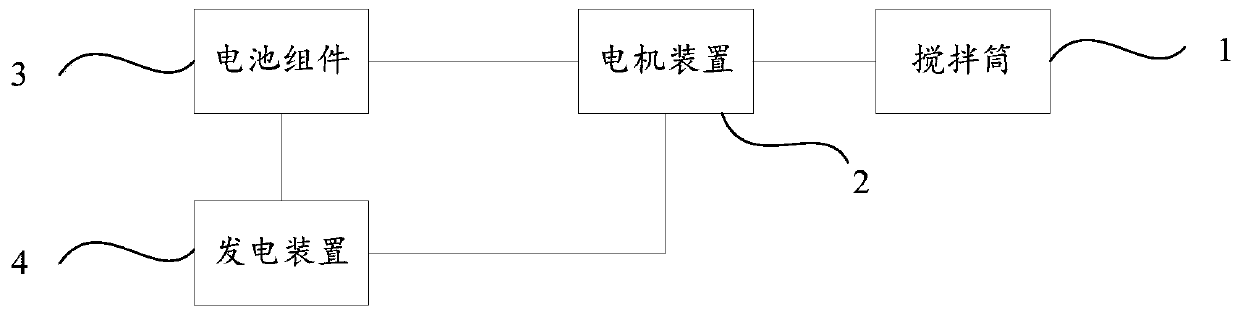
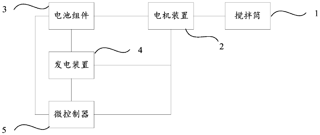
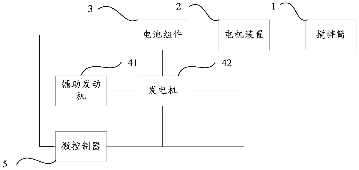
[0048] Refer below Figure 1 to Figure 3 A mixer truck bodywork drive system according to some embodiments of the invention is described.

[0049] Such as figure 1 As shown, an embodiment of the p...


PUM


Abstract

The invention provides an agitating lorry upper-installed driving system and an agitating lorry upper-installed driving control method. An agitating lorry comprises a vehicle chassis and an agitatingbarrel arranged on the vehicle chassis. A main engine is arranged on the vehicle chassis. The agitating lorry upper-installed driving system comprises a motor device, a battery assembly and a power generation device. The motor device is in transmission connection with the agitating barrel so that the agitating barrel is driven to rotate through the motor device. The battery assembly is in electricconnection with the motor device. The power generation device is in electric connection with the motor device and provides electric energy for the motor device, and the power generation device is inelectric connection with the battery assembly so that the battery assembly is charged by the power generation device. According to the technical scheme, the agitating lorry upper-installed driving system can run independently and do not need to rely on output power of the main motor of the agitating lorry; working efficiency can be improved efficiently, and the agitating quality of concrete is prevented from being influenced by stop of agitating barrel rotation caused by insufficient power; besides, load of the main motor does not need to be increased, and reduction of main engine emission andpollution emission is benefited; and the cost is lowered.

Description

technical field [0001] The invention relates to the field of driving control of a mixing device of a mixer truck, in particular to a mixer truck bodywork drive system and a mixer truck bodywork drive control method. Background technique [0002] At present, concrete mixer trucks have been widely used in the field of construction engineering. In order to drive the mixing drum on the mixer truck to rotate and realize concrete mixing operations, most existing mixer trucks use a power take-off connected to the main engine to drive the hydraulic mechanism to drive the mixing drum. However, the top-mounted drive system of the mixer truck depends on the power provided by the main engine and cannot work independently. The rotation of the mixing drum is affected by the speed of the main engine, and the mixing drum consumes part of the output power of the main engine, which increases the load on the main engine. The structure and control system of the force device are relatively compl...

Claims


Application Information

Patent Timeline
Patent Type & Authority Applications(China)
IPC IPC(8): B28C5/42
CPCB28C5/421B28C5/422H02J7/1415H02J2310/48
Inventor 田飞云王文中罗尧
Owner SANY SPECIAL PURPOSE VEHICLE CO LTD
Why Eureka
Try Eureka