Gas flow limiting structure of desulfurization and denitration dust collector

A technology of desulfurization, denitrification, and dust collector, which is applied in the direction of gas treatment, exhaust gas equipment, chemical instruments and methods, etc., and can solve problems such as inconvenient fixing and inability to limit flow

Inactive Publication Date: 2019-08-16
DATANG YUNCHENG POWER GENERATION CO LTD
View PDF6 Cites 2 Cited by
  • Summary
  • Abstract
  • Description
  • Claims
  • Application Information

AI Technical Summary

Problems solved by technology

[0005] The purpose of the present invention is to provide a gas flow limiting structure for desulfurization, denitrification and dust removal to solve the problems of inconvenient fixing and inability to limit the flow in the above-mentioned background technology

Method used


Image

  • Gas flow limiting structure of desulfurization and denitration dust collector
  • Gas flow limiting structure of desulfurization and denitration dust collector
  • Gas flow limiting structure of desulfurization and denitration dust collector

Examples


Embodiment Construction

[0020] The following will clearly and completely describe the technical solutions in the embodiments of the present invention with reference to the accompanying drawings in the embodiments of the present invention. Obviously, the described embodiments are only some, not all, embodiments of the present invention. Based on the embodiments of the present invention, all other embodiments obtained by persons of ordinary skill in the art without making creative efforts belong to the protection scope of the present invention.

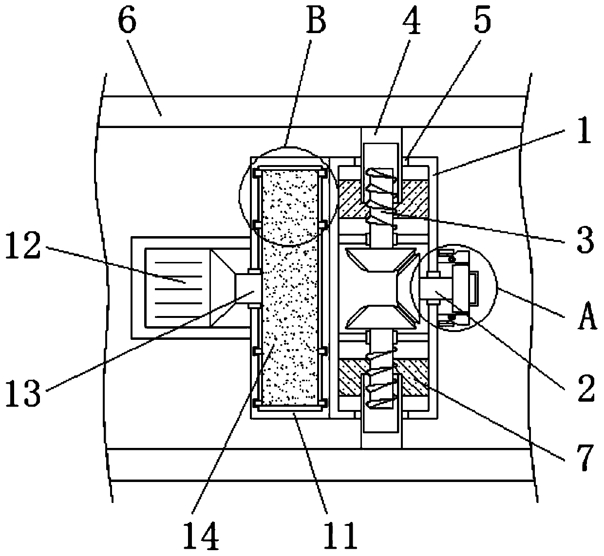
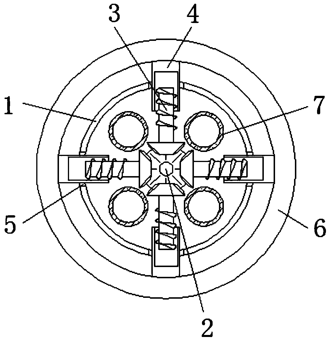
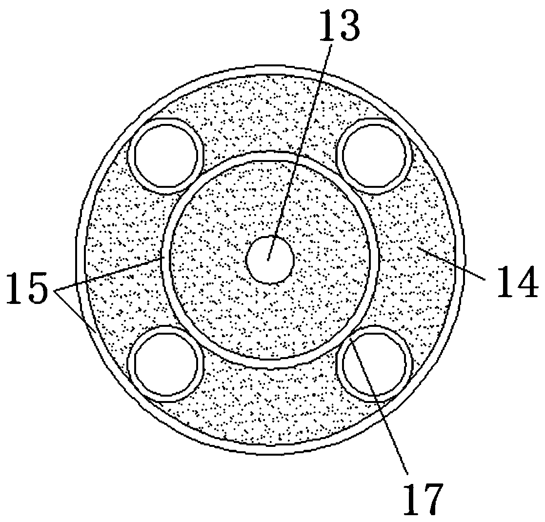
[0021] see Figure 1-5 , the present invention provides a technical solution: a gas flow limiting structure for desulfurization, denitrification and dust removal, including a fixed shell 1, a control rod 2, a linkage rod 3, a linkage sleeve 4, a working tank 5, a flue gas channel 6, a first flow limiting Tube 7, fixed cylinder 8, extrusion sleeve 9, extrusion block 10, current limiting shell 11, motor 12, power rod 13, rotating plate 14, movable strip 15, seal...


PUM


Abstract

The invention discloses a gas flow limiting structure of a desulfurization and denitration dust collector. The structure comprises a fixing shell, a control rod and linkage rods; the control rod is installed on the fixing shell, the control rod is connected with the linkage rods, and the linkage rods are installed on the fixing shell; each linkage rod is installed in one corresponding linkage sleeve, each linkage sleeve is installed in one corresponding working groove, the working grooves are arranged in the fixing shell, and each linkage sleeve is connected with the inner wall of one corresponding flue gas passage; first flow limiting pipes are installed in the fixing shell, each pressing sleeve is connected with one corresponding pressing block, a flow limiting shell is fixed to the fixing shell, and a power rod is installed on the flow limiting shell; each movable strip is installed in one corresponding sealing guide groove; and second flow limiting pipes are installed on a rotatingplate. According to the gas flow limiting structure of the desulfurization and denitration dust collector provided by the invention, the structure with a fixing function is designed, so that the problem of inconvenient fixing is solved; and at the same time, the structure with a flow limiting function is designed, so that the problem that a conventional device cannot limit a flow is solved.

Description

technical field [0001] The invention relates to the technical field of dust collectors, in particular to a gas flow limiting structure of a desulfurization and denitrification dust collector. Background technique [0002] Desulfurization, denitrification and dust collector is a kind of purification equipment installed on the flue gas pipeline. By filtering the gas in the flue gas pipeline, desulfurization, denitrification and dust removal, the gas discharged from the flue gas pipeline meets environmental protection standards. The desulfurization and denitrification dust collector belongs to environmental protection. One of the devices. [0003] Because the gas flow rate in different flue gas pipes is different, the gas purification rate of the desulfurization and denitrification dust collector is fixed. Effective desulfurization, denitrification and dust removal for gas. At the same time, the traditional flow limiting device is usually installed at the end of the flue gas p...

Claims


Application Information

Patent Timeline
Patent Type & Authority Applications(China)
IPC IPC(8): B01D53/00B01D53/50B01D53/48B01D49/00F23J15/02F23J13/00
CPCB01D49/00B01D53/00B01D53/48B01D53/50B01D2258/0283
Inventor 王腾飞房吉国任庆朋
Owner DATANG YUNCHENG POWER GENERATION CO LTD
Why Eureka
Try Eureka