Cable production device

A technology for producing devices and cables, applied in the direction of wire drawing dies, etc., can solve the problems of the wire core unable to keep the center line of the wire drawing die hole level, unable to automatically calibrate, and the wire core scratching, etc.

Active Publication Date: 2019-08-16
CHONGQING RUIPU CABLE
View PDF6 Cites 2 Cited by
  • Summary
  • Abstract
  • Description
  • Claims
  • Application Information

AI Technical Summary

Problems solved by technology

[0004] The purpose of the present invention is to provide a cable production device to solve the problem that the metal wire core cannot be automatically calibrated during...

Method used


Image

  • Cable production device
  • Cable production device
  • Cable production device

Examples


Embodiment 1

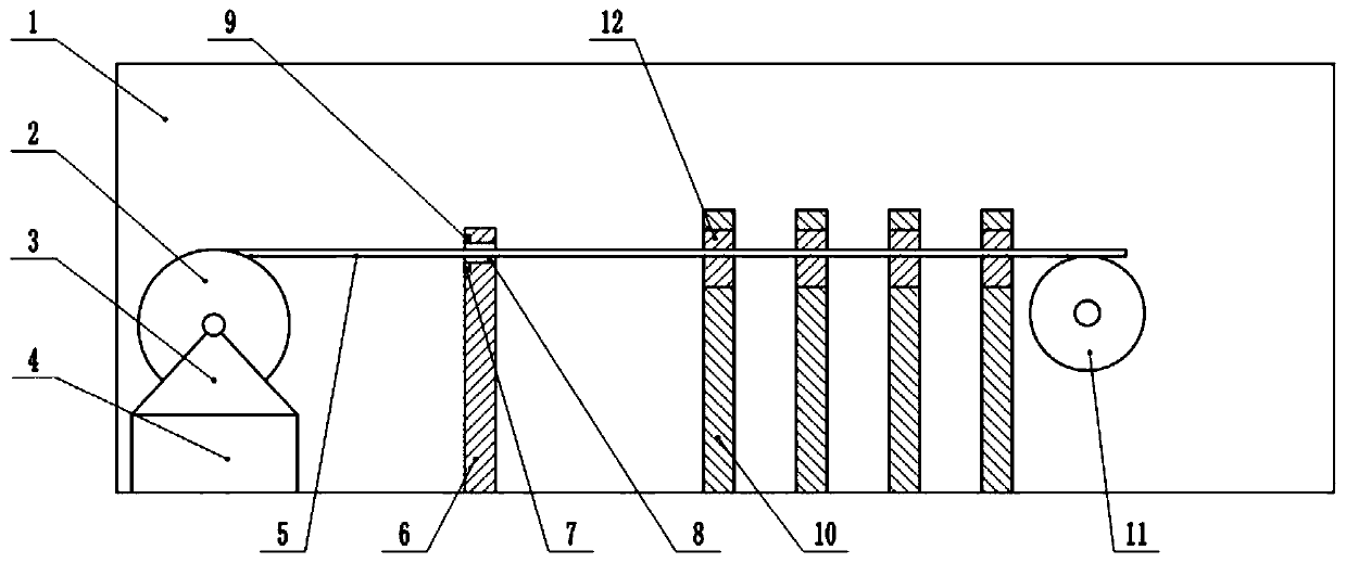
[0038] Embodiment one is basically as attached figure 1 Shown: the production device of the cable, including the motor and the housing 1, and the housing 1 also includes a coiling mechanism, a positioning calibration mechanism and a wire pulling mechanism from left to right. The winding mechanism includes, from top to bottom, a winding wheel 2 for winding the wire core 5, a base 3 for supporting the winding wheel 2, and a telescopic cylinder 4 for lifting the base 3, and the lower end of the telescopic cylinder 4 is fixedly connected by screws. At the inner bottom of the housing 1, the telescopic cylinder 4 is used to push the upper end of the base 3 up and down, and the bottom of the base 3 is fixedly connected together by screws. 4 Model: JB400×S, motor model: Y-180L-8.

[0039]The positioning and calibration mechanism includes a calibration plate 6. The bottom of the calibration plate 6 is fixedly connected to the inner bottom of the housing 1 through screws. The upper end...

Embodiment 2

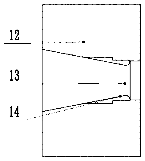
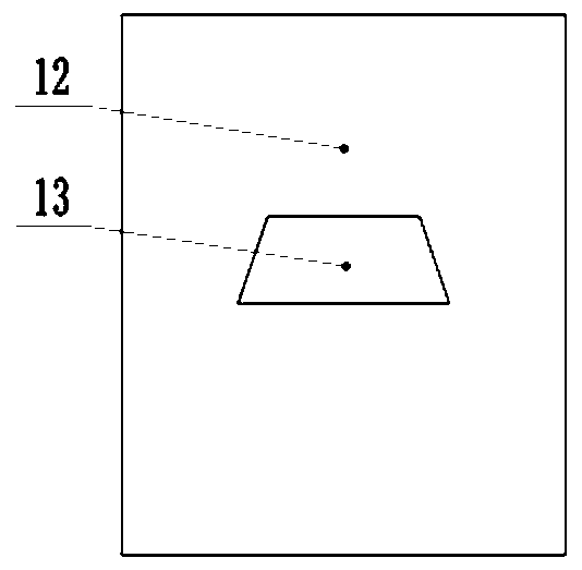
[0048] Embodiment two is basically as attached Figure 4 As shown, the difference between the second embodiment and the first embodiment lies in the reel 2 and the base 3, the upper end of the base 3 is provided with a groove for accommodating the reel 2, the reel 2 is hollow inside, the right side is open, and the left side is open. The side is closed, and arc-shaped magnetic strips 16 matching the shape of the inner wall of the reel 2 are respectively bonded to the opening on the right side, and the polarities of the upper and lower arc-shaped magnetic strips 16 are opposite, and the left side of the reel 2 The coaxial fixedly is connected with rotating shaft 15, and rotating shaft 15 passes the left side wall of reel 2 and is connected with the left side wall of base 3 grooves rotatably, on the groove right side wall, is fixedly connected with fixed rod 18 by screw, fixed rod 18 Extend from the right side of the reel 2 into the inside of the reel 2, such as Figure 5 As sh...


PUM


Abstract

The invention relates to the field of cable processing, in particular to a cable production device. The cable production device comprises a cable wire winding mechanism, a positioning and calibrationmechanism and a wire drawing mechanism, wherein the cable wire winding mechanism sequentially comprises a cable wire winding wheel, a base and a telescopic air cylinder; the cable wire winding wheel is rotationally connected with the base, the positioning and calibrating mechanism comprises a calibration plate, a cable wire through hole is formed in the calibration plate, the cable wire drawing mechanism comprises a cable wire drawing plate, a cable wire drawing die hole is formed in the cable wire drawing plate, and the cable wire drawing die hole and the center line of the cable wire throughhole are located on the same horizontal line; the cable production device further comprises a control circuit used for controlling a telescopic rod to ascend and descend, the control circuit is a disconnected circuit, breakpoints are respectively arranged at the bottom of a port of one end of an inlet wire of the cable wire through hole and the top of a port of one end of the inlet wire of the wire through hole. In this way, the problem that a wire core is scratched due to the fact that the metal wire core cannot be automatically calibrated in the cable wire drawing process is solved, and thecable production device is mainly used for cable production factories.

Description

technical field [0001] The invention relates to the field of cable processing, in particular to a cable production device. Background technique [0002] Cable is an indispensable connecting cable in electrical equipment. At present, the equipment used in the production of wire and cable in my country mainly includes tube twisting machine, cage twisting machine and frame twisting machine, but usually the wires processed by these equipment The cross-section of the internal metal core of the cable is mostly circular. If it is a circular metal core, it will be twisted in the twisted wire (the twisted wire is an essential and important processing step in the cable processing process, and the twisted wire is a twisted single wire. When rotating around the stranded wire shaft at a constant angular velocity and the stranded wire moves forward at a constant speed), gaps are likely to appear between adjacent circular cores. During subsequent processing, dust or some accumulations are ea...

Claims


Application Information

Patent Timeline
IPC IPC(8): B21C1/04B21C1/14B21C3/02B21C47/34
CPCB21C1/04B21C1/14B21C3/02B21C47/3408
Inventor 王云彭书礼吴小松
Owner CHONGQING RUIPU CABLE
Why Eureka
Try Eureka