
Tire ring splitting machine

A ring cutting machine and tire technology, applied in recycling technology, plastic recycling, etc., can solve problems such as high work intensity and injuries

Pending Publication Date: 2019-08-16
GENOX RECYCLING TECH
View PDF0 Cites 5 Cited by
  • Summary
  • Abstract
  • Description
  • Claims
  • Application Information

AI Technical Summary

Problems solved by technology

[0003] However, the existing operation of separating the outer ring and the inner ring of the tire mainly relies on manual work, which not only has high work intensity, but also causes workers to be injured during the ring cutting process.

Method used


Image

  • Tire ring splitting machine
  • Tire ring splitting machine
  • Tire ring splitting machine

Examples


Embodiment Construction

[0024] Below, the present invention will be further described in conjunction with the accompanying drawings and specific implementation methods. It should be noted that, under the premise of not conflicting, the various embodiments described below or the technical features can be combined arbitrarily to form new embodiments. .

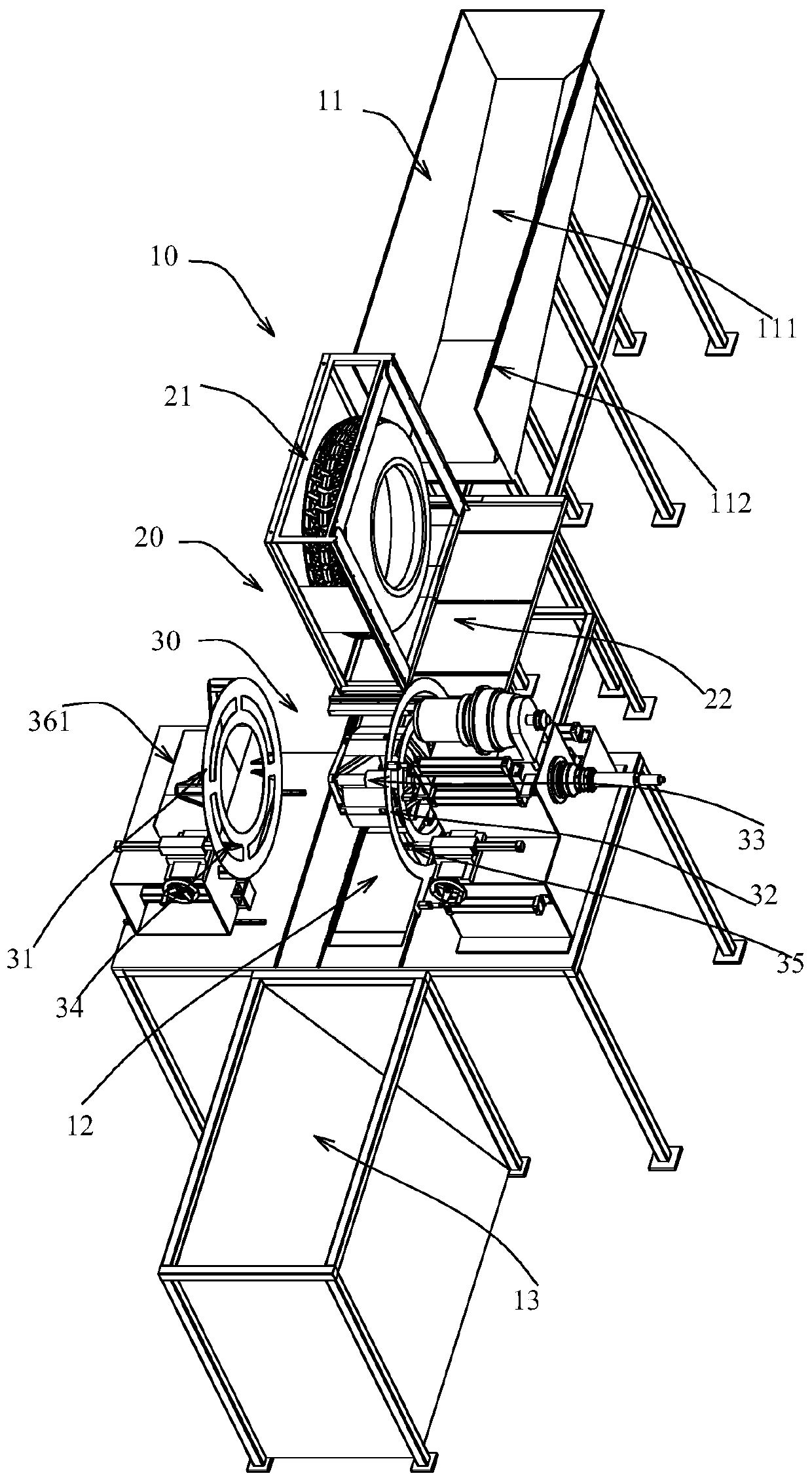
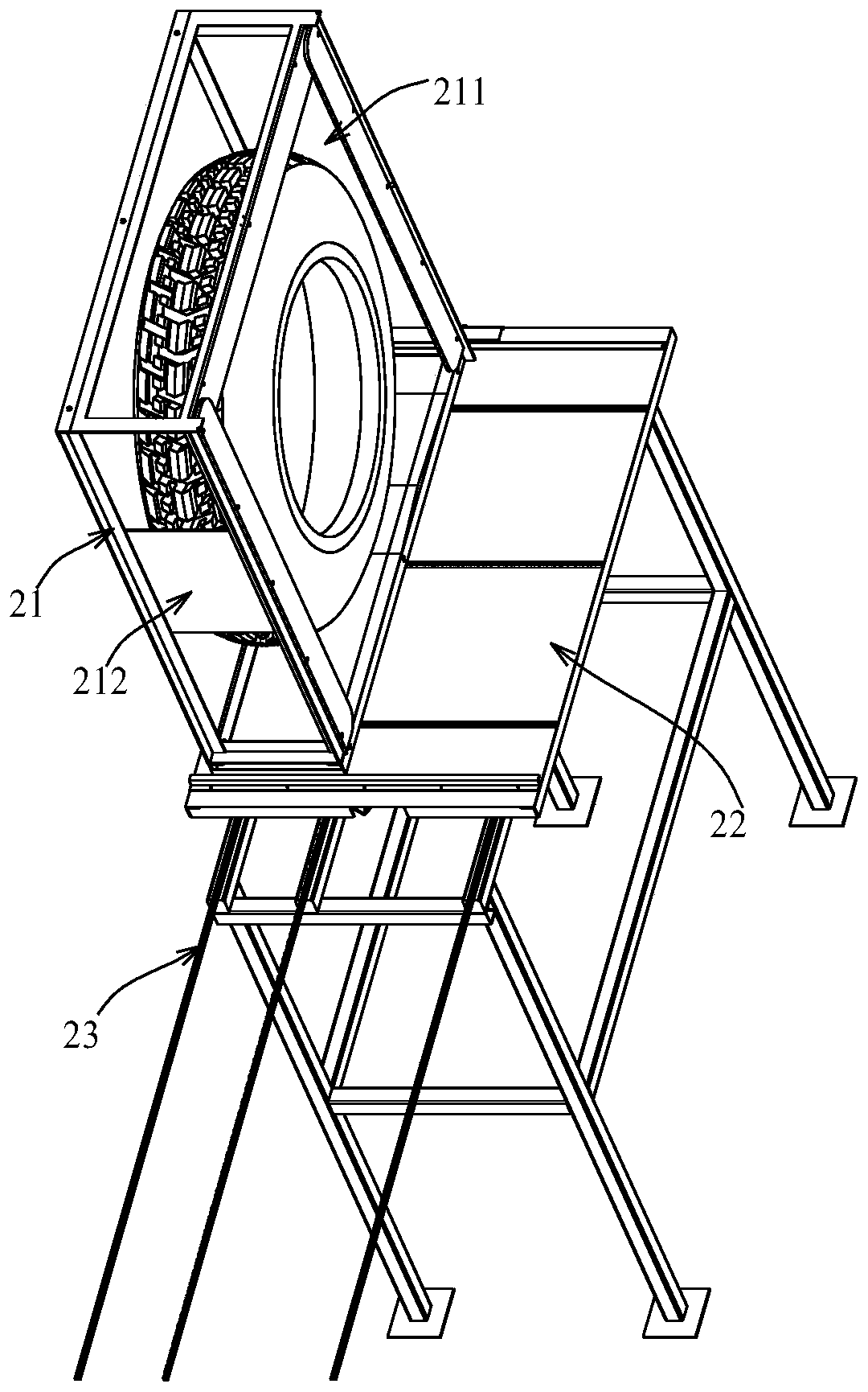
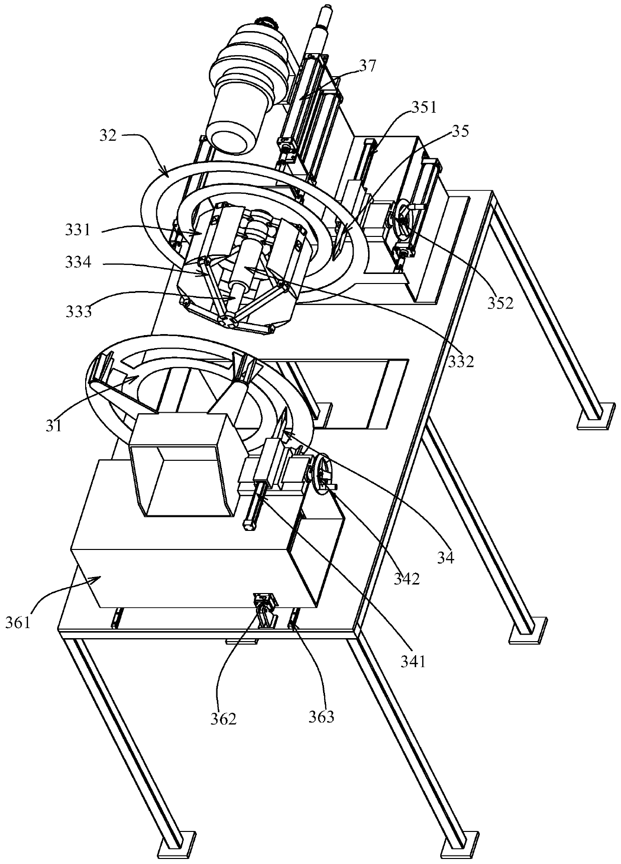
[0025] Such as figure 1 , figure 2 as well as image 3 The shown tire ring cutting machine includes a body 10, a positioning mechanism 20 and a ring cutting mechanism 30, and a positioning station and a ring cutting station are arranged on the body 10. The positioning mechanism 20 is installed at the positioning station, and It can move from the positioning station to the ring cutting station. And this positioning mechanism 20 is used for tire is positioned, when it moves to ring cutting station by positioning station, can drive the tire in positioning mechanism 20 to move to ring cutting station by positioning station.

[0026] Specifically, the ...


PUM


Abstract

The invention discloses a tire ring splitting machine. The tire ring splitting machine comprises a machine bod, a positioning mechanism and a ring splitting mechanism, wherein the ring splitting mechanism comprises a first fixing part, a second fixing part, a first cutting knife, a second cutting knife and an inner ring fixing assembly, the first fixing part and the second fixing part are arrangedat an interval, the first fixing part can move towards the position close to or away from the second fixing part in the axial direction of the first fixing part, the inner ring fixing assembly is connected in the second fixing part in a penetrating mode and is pivoted to the machine body, the inner ring fixing assembly is used for being inserted into the inner periphery of an inner ring of a tireand abutting against the inner periphery of the inner ring of the tire when the positioning mechanism moves to a ring splitting station, the first fixing part is used for fixing the tire on the innerring fixing assembly to move towards the position close to the second fixing part so as to enable the tire to be clamped between the first fixing part and the second fixing part, the first cutting knife is arranged on the machine body, and the second cutting knife is arranged on the machine body. According to the tire ring splitting machine, the inner ring and the outer ring of the tire can be separated.

Description

technical field [0001] The invention relates to the technical field of tire recycling equipment, in particular to a tire ring cutting machine. Background technique [0002] At present, along with the progress of society and the development of economy, various vehicles have become indispensable consumables for people's life and work. And tire is the requisite part of car, thereby its mass production and application cause the waste of rubber raw material. The existing practice is to recycle tires to avoid waste of resources. When recycling tires, it is necessary to cut off the inner ring with better rubber quality in the tire and separate it from the outer ring. Then the inner ring is moved to the inner ring and steel wire separation equipment for further processing, and the rubber and steel wire of the inner ring are separated and recycled separately. The outer ring is moved to the outer ring processing equipment for strip and block processing, which is convenient for subs...

Claims


Application Information

Patent Timeline
Patent Type & Authority Applications(China)
IPC IPC(8): B29B17/00
CPCB29B17/00B29B2017/0021Y02W30/62
Inventor 陈新准胡郝蒋伟
Owner GENOX RECYCLING TECH
Learn More