Method and device for controlling automobile electronic rearview mirror

A technology of automotive electronics and control methods, applied in optical observation devices, vehicle components, transportation and packaging, etc., can solve problems such as stimulating the driver's eyes, affecting the driver's driving safety, and being unsuitable for the driver's driving habits, achieving convenient use and driving safety. Effect

Inactive Publication Date: 2019-08-16
ANSHAN KEDA INTERNET OF THINGS SCI & TECH
View PDF8 Cites 3 Cited by
  • Summary
  • Abstract
  • Description
  • Claims
  • Application Information

AI Technical Summary

Problems solved by technology

[0003] 1. If the installation position of the display screen used to display the image of the rear-view camera is installed at the front of the driver's seat (such as a reversing image), it will conflict with the driver's regular driving observation habits and is not suitable for the driver's driving habits;
[0004] 2. If the display screen is installed on both sides of the car, close to the position of the external rearview mirror, it can facilitate the driver's driving and observation habits, but the brightness of the display screen, especially at night, will stimulate the driver's eyes and affect the driver Driving safety, so a control method that can display and not display according to the driver's needs is needed to solve this problem

Method used


Image

  • Method and device for controlling automobile electronic rearview mirror
  • Method and device for controlling automobile electronic rearview mirror
  • Method and device for controlling automobile electronic rearview mirror

Examples


Embodiment Construction

[0033] The specific embodiments provided by the present invention will be described in detail below in conjunction with the accompanying drawings.

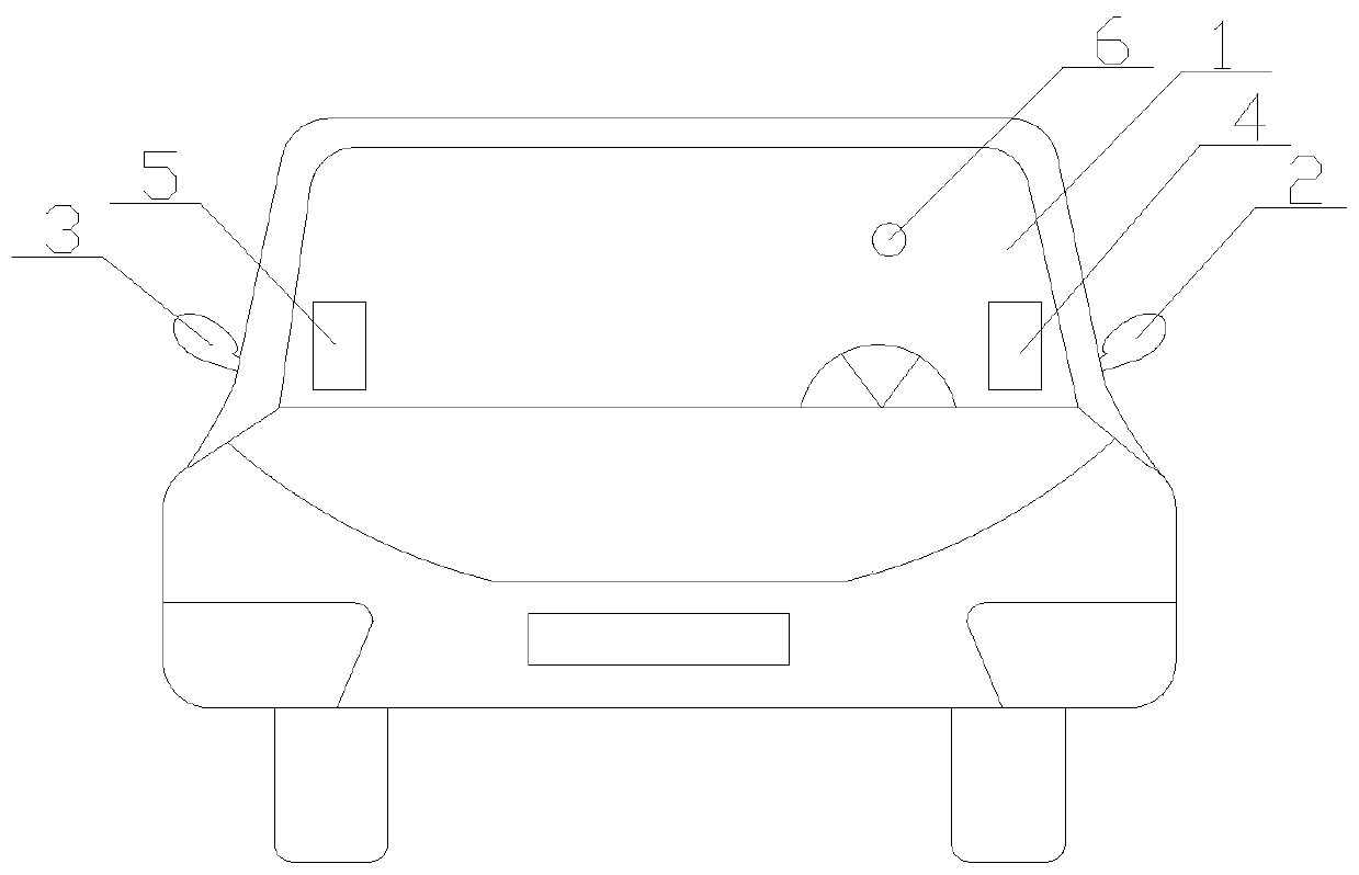
[0034] Such as figure 1 Shown, a kind of control method of automobile electronic rearview mirror comprises the steps:

[0035] Step 1, respectively install one or more traffic collecting cameras 2 and 3 on the left and right rearview mirrors of the car;

[0036] Step 2, install a display screen 4 and 5 on the left and right sides of the front of the car respectively;

[0037] Step 3, install the driver's head feature recognition camera 6 in the car and on the front windshield 1;

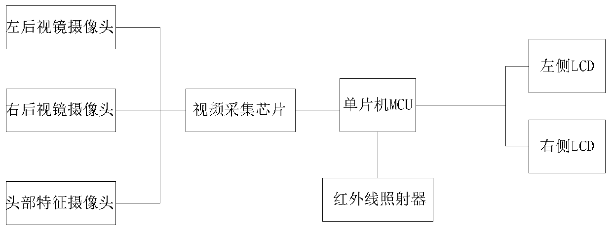
[0038] Step 4, the main control MCU first collects the driver's head features through the driver's head feature recognition camera 6, and after video processing, judges the moving action of the driver's pupils, taking into account the judgment of the driver's head deflection action;

[0039] Step 5, collect the road conditions on the left and right si...


PUM


Abstract

The invention provides a method and device for controlling an automobile electronic rearview mirror. The method for controlling an automobile electronic rearview mirror includes the steps that displayscreens are correspondingly installed on the left side and the right side of the front part inside an automobile; a driver head feature recognition camera is installed on a front windshield inside ofthe automobile; a master MCU collects the driver head feature through the driver head feature recognition camera firstly, judges the driver pupil movement and the driver head deflection at the same time after video is processed; when the master MCU judges that the driver pupil moves to the left, the road condition information on the left side of an automobile body is displayed on the left displayscreen; and when the MCU judges that the driver pupil moves to the right, the road condition information on the right side of the automobile body is displayed on the right display screen. Rear-view image display screens are correspondingly installed on the left side and the right side of the front part inside the automobile, and the display and non-display are controlled according to the driver pupil and head rotation, so that using by drivers is more convenient, and driving is safer.

Description

technical field [0001] The invention relates to the field of automobile intelligent control, in particular to a method and device for controlling an automobile electronic rearview mirror. Background technique [0002] At present, automobiles have entered every family, and the number of automobiles has also increased greatly. In the prior art, there is a technology of installing a camera in the rearview mirror of the automobile, but the following technical problems still exist in the prior art: [0003] 1. If the installation position of the display screen used to display the image of the rear-view camera is installed at the front end of the driving seat (such as a reversing image), it will conflict with the driver's regular driving observation habits and is not suitable for the driver's driving habits; [0004] 2. If the display screen is installed on both sides of the car, close to the position of the external rearview mirror, it can facilitate the driver's driving and obse...

Claims


Application Information

Patent Timeline
Patent Type & Authority Applications(China)
IPC IPC(8): B60R1/12B60R1/00
CPCB60R1/12B60R1/00B60R2001/1253B60R2300/105B60R2300/804
Inventor 朱成元李春宇贾福禄张中成刘洋
Owner ANSHAN KEDA INTERNET OF THINGS SCI & TECH
Why Eureka
Try Eureka