Embedded drainage pipe structure capable of being rapidly replaced

A drainage pipe and pre-embedded technology, which is applied in the direction of sewer pipe system, waterway system, water supply device, etc., can solve the problems of troublesome replacement construction, aging drainage pipe structure, and non-replacement, so as to reduce maintenance cost and avoid difficult replacement , The effect of reducing the installation cost

Pending Publication Date: 2019-08-16
CHINA RAILWAY SIYUAN SURVEY & DESIGN GRP
View PDF0 Cites 1 Cited by
  • Summary
  • Abstract
  • Description
  • Claims
  • Application Information

AI Technical Summary

Problems solved by technology

[0004] At present, the pre-embedded drainage pipes are buried during the construction of the tunnel or the structural floor of the station, and the construction of the corresponding structure above the drainage pipes is completed after the embedding is completed, that is, the pre-embedded drainage pipes in the prior art are fixed in the tunnel structure or underground structure Among them, although this type of drainage pipe structure can meet the needs of the connection between the sand pit and the waste water tank to a certain extent, it also has a relatively large defect, that is, once the burial is completed, it cannot be replaced, or the replacement construction is extremely troublesome
At the same time, during the long-term use of the drainage pipe structure, the aging and blockage of the drainage pipe structure are prone to occur, which will lead to water accumulation and water seepage in the underground line or tunnel line, affecting the normal operation of the track structure, and the replacement of the drainage pipe structure The construction is cumbersome, and the normal use of the track line will be greatly affected during the replacement process, resulting in an increase in the application cost of the underground line or tunnel line

Method used


Image

  • Embedded drainage pipe structure capable of being rapidly replaced
  • Embedded drainage pipe structure capable of being rapidly replaced
  • Embedded drainage pipe structure capable of being rapidly replaced

Examples


Embodiment Construction

[0032] In order to make the object, technical solution and advantages of the present invention clearer, the present invention will be further described in detail below in conjunction with the accompanying drawings and embodiments. It should be understood that the specific embodiments described here are only used to explain the present invention, not to limit the present invention.

[0033] In addition, the technical features involved in the various embodiments of the present invention described below can be combined with each other as long as they do not constitute a conflict with each other.

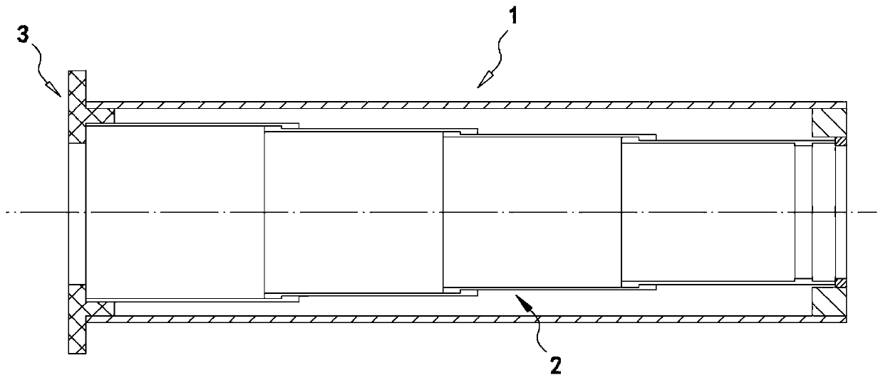
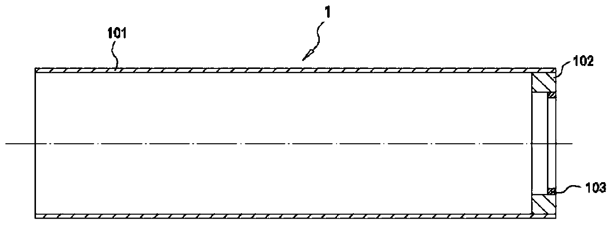
[0034]In the preferred embodiment of the present invention, the structure of the embedded drainage pipe that can be quickly replaced is as follows: figure 1 As shown in the figure, it is not difficult to see from the diagram that it consists of an outer sleeve 1, an inner sleeve 2 and a cover 3, wherein the outer sleeve 1 and the inner sleeve 2 are respectively in a tubular structure, ...


PUM


Abstract

The invention discloses an embedded drainage pipe structure capable of being rapidly replaced, and belongs to the technical field of water supply and drainage in civil engineering. An outer sleeve andan inner sleeve which can be coaxially matched are arranged, and the outer sleeve is embedded between a sand pit and a waste water tank, and the inner sleeve can be correspondingly nested and lappedin the outer sleeve. The inner sleeve correspondingly realizes the corresponding communication between the sand pit and the waste water tank, and the drainage of waste water is realized. Once the inner sleeve is aged, blocked, damaged and the like, the inner sleeve can be correspondingly taken out and replaced quickly, and the excavation of a large amount of earthwork in the drainage pipe replacement process is effectively avoided. The embedded drainage pipe structure capable of being rapidly replaced is simple in structure and simple and convenient to arrange, the arrangement and replacementof embedded drainage pipes between the sand pit and the waste water tank can be quickly realized, the steps of maintenance and replacement of the embedded drainage pipes are simplified, the arrangement and replacement period of the embedded drainage pipes is shortened, the application cost of the embedded drainage pipes is reduced, and better application prospect and popularization value are achieved.

Description

technical field [0001] The invention belongs to the technical field of civil engineering water supply and drainage, and in particular relates to a rapidly replaceable pre-embedded drainage pipe structure. Background technique [0002] In civil construction projects, in order to meet the needs of water supply and drainage, it is often necessary to pre-embed a certain number of drainage pipes in the main structure of the project. Taking railway traffic engineering as an example, smooth drainage in the track area is an important condition to ensure the normal operation of trains and reduce track defects, especially for underground lines and tunnel lines, it is particularly important to ensure smooth drainage in the track area. [0003] In the prior art, the track area drainage method commonly used in the underground line or tunnel line of railway traffic engineering is: set longitudinal drainage ditches on both sides of the track bed respectively, and divert the seepage water f...

Claims


Application Information

Patent Timeline
Patent Type & Authority Applications(China)
IPC IPC(8): E03F3/04
CPCE03F3/04
Inventor 罗伟孙立王森荣朱彬张世杰林超全顺喜刘永存
Owner CHINA RAILWAY SIYUAN SURVEY & DESIGN GRP
Why Eureka
Try Eureka