Fuel filling device of engine
A filling device and engine technology, applied in the direction of engine components, combustion engines, machines/engines, etc., can solve the problems of inconvenient installation of fuel tanks, and achieve the effect of improving convenience and achieving centering alignment
- Summary
- Abstract
- Description
- Claims
- Application Information
AI Technical Summary
Problems solved by technology
Method used
Image
Examples
Embodiment 1
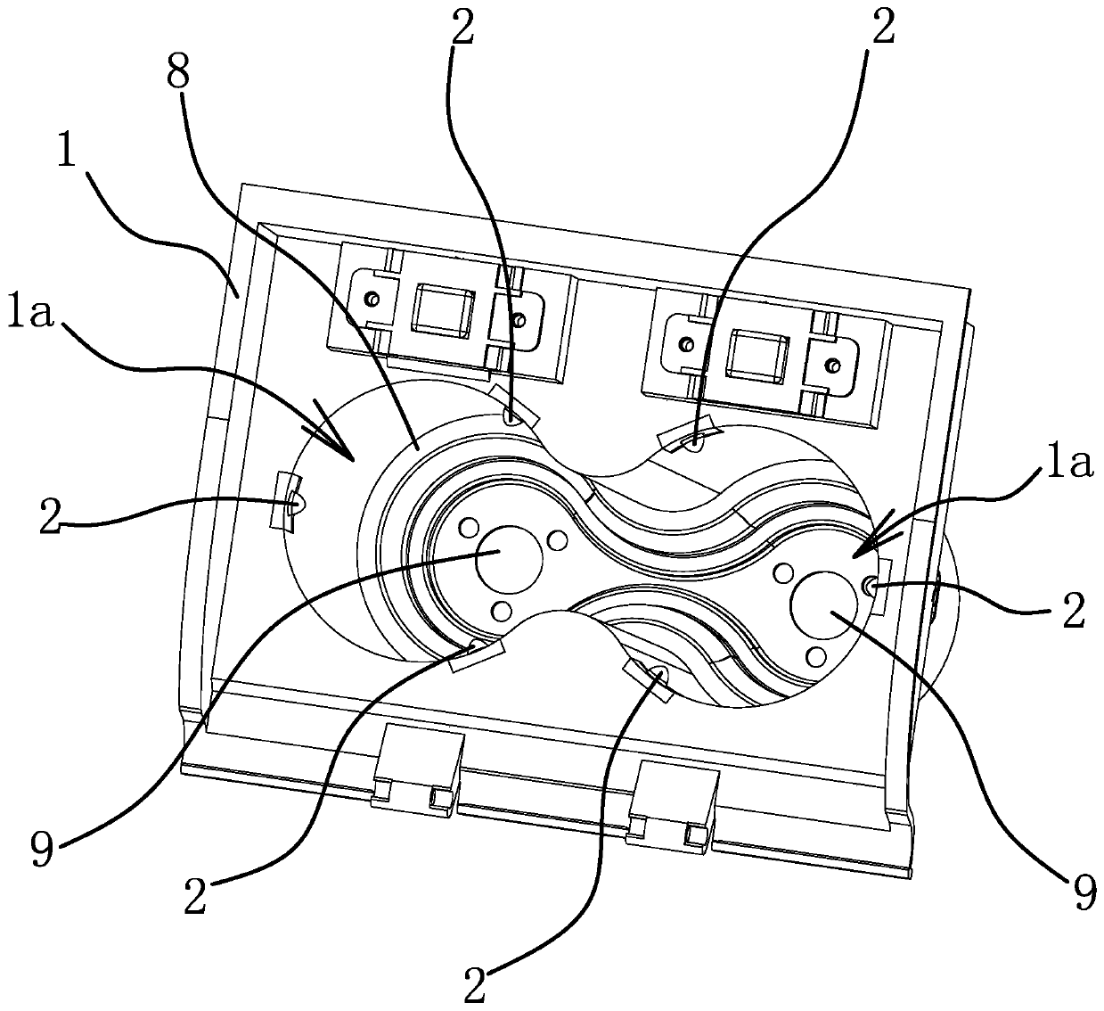
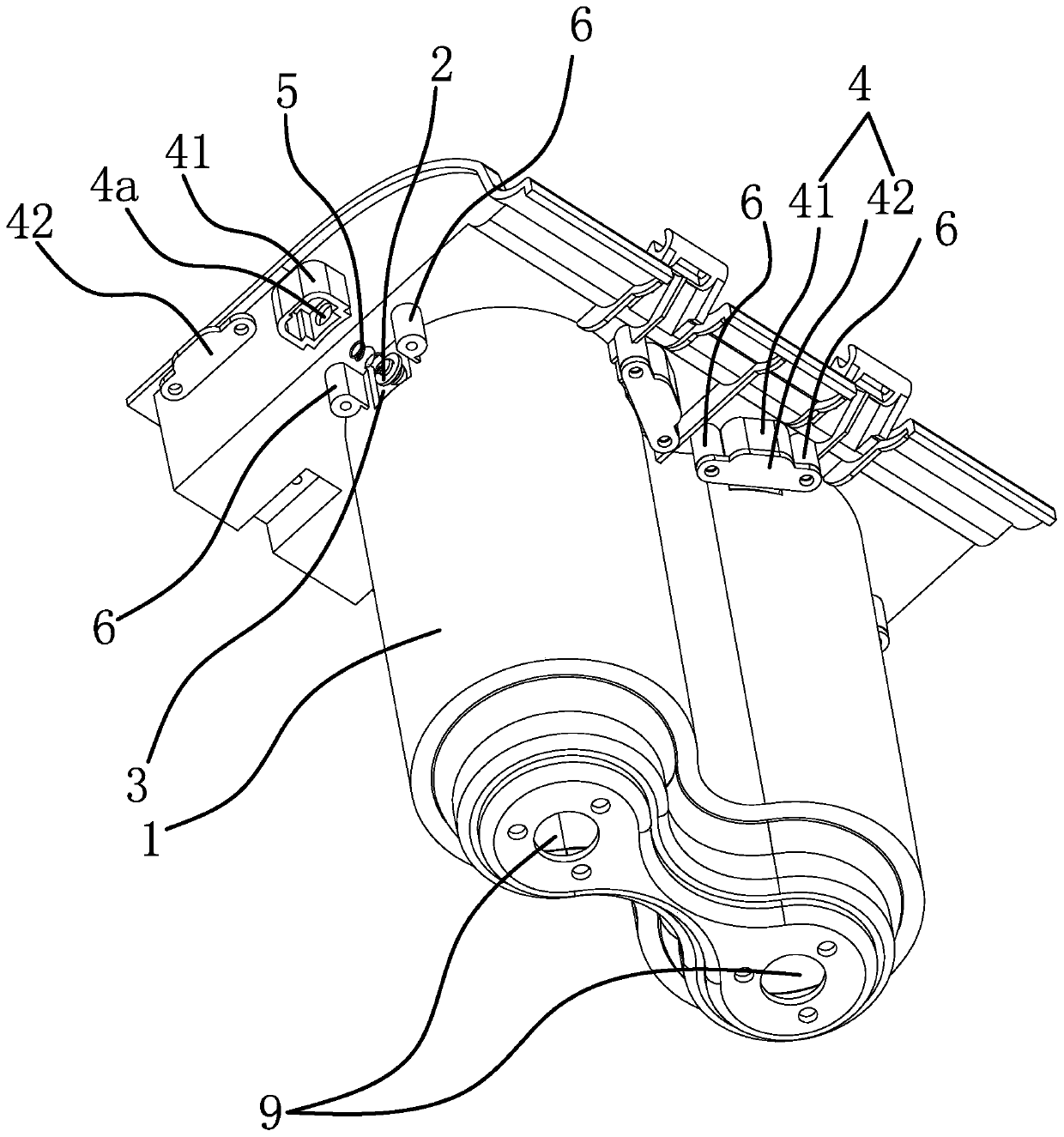
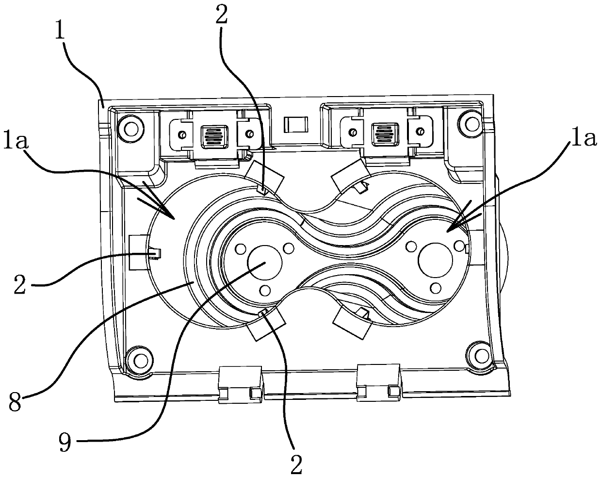
[0030] Specifically, as figure 1 As shown, the fuel filling device of the engine includes a housing 1, and the housing 1 has a columnar inner chamber 1a for filling the fuel tank a. In this embodiment, the inner chamber 1a is cylindrical and has two, two Open up between the two lumens 1a. The inner wall of the inner cavity 1a is used to guide and cooperate with the front end of the fuel tank a. On the inner wall of the inner chamber 1a near the bottom, there is an outwardly protruding stop ring portion 8 . The inner wall of the inner cavity 1a near the bottom has an auxiliary surface which is consistent with the shape of the front end of the fuel tank a, and the auxiliary surface is located below the stop ring part 8 . At the same time, there are at least three positioning pieces 2 evenly arranged around the center line of the cavity 1a in the rear position of the inner wall of the cavity 1a, and the positioning pieces 2 are arranged along the direction perpendicular to the ...
Embodiment 2
[0034] The technical solution in this embodiment is basically the same as the technical solution in Embodiment 1, the difference is that, as image 3 with Figure 4 As shown, in this embodiment, the positioning member 2 is an elastic piece capable of elastic deformation, and the elastic piece is fixed on the inner wall of the inner chamber 1a. Specifically, the elastic sheet is V-shaped and arranged in the axial direction, and an installation groove 11 is opened on the inner wall of the inner cavity 1a. On the edge of the port, a clamping plate 12 is arranged in the mounting groove 11 , and the clamping plate 12 is located at one end of the mounting groove 11 and is snap-connected with the housing 1 . The above design of the installation structure of the positioning member 2 enables the positioning member 2 to be easily and conveniently installed on the housing 1, thereby improving the assembly efficiency of the device.
Embodiment 3
[0036] The technical solution in this embodiment is basically the same as the technical solution in Embodiment 1, the difference is that, as Figure 5 As shown, in this embodiment, the inner wall of the inner cavity 1a has a mounting through groove 7, and the positioning member 2 is integrally formed on the inner wall of the inner cavity 1a and is located in the positioning claw of the mounting through groove 7, and the positioning claw can be opposite to the inner wall. The inner wall of the chamber 1a elastically shrinks. Through the above design of the positioning part 2, the positioning part 2 does not need to be assembled, which is beneficial to improve the assembly efficiency of the device.
PUM
 Abstract
Description
Claims
Application Information
 - R&D
- Intellectual Property
- Life Sciences
- Materials
- Tech Scout
- Unparalleled Data Quality
- Higher Quality Content
- 60% Fewer Hallucinations
Browse by: Latest US Patents, China's latest patents, Technical Efficacy Thesaurus, Application Domain, Technology Topic, Popular Technical Reports.
© 2025 PatSnap. All rights reserved.Legal|Privacy policy|Modern Slavery Act Transparency Statement|Sitemap|About US| Contact US: help@patsnap.com


