a magnetic bearing
A technology of magnetic bearings and rotating shafts, applied in the field of magnetic bearings, can solve the problems of non-adjustable permanent magnet bias flux, little improvement in inherent stiffness, and high difficulty in manufacturing and assembly, so as to improve levitation accuracy, reduce control difficulty, and high inherent stiffness Effect
- Summary
- Abstract
- Description
- Claims
- Application Information
AI Technical Summary
Problems solved by technology
Method used
Image
Examples
Embodiment 1
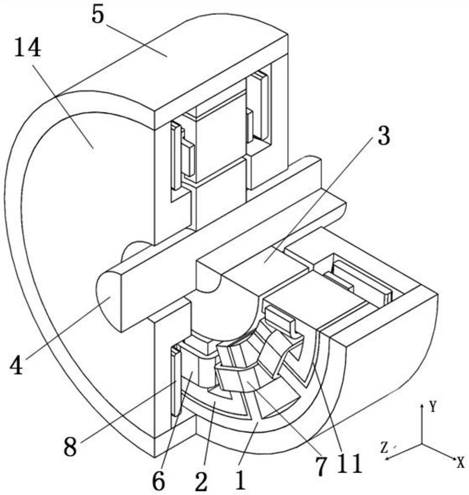
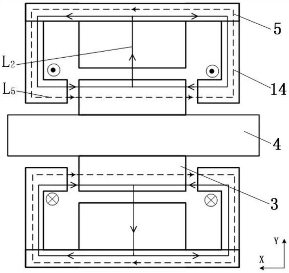
[0043] Such as figure 1 As shown, the magnetic bearing provided by the embodiment of the present invention includes an annular magnetic yoke 5, a first radial stator 1 disposed inside the annular magnetic yoke 5, a second radial stator 2, an axial stator 14, a radial offset Coil 7 , shaft / radial levitation coil 6 , rotor 3 and shaft 4 .
[0044] The rotor 3 is a hollow cylindrical structure and is sheathed on the rotating shaft 4 . The first radial stator 1 is annular and coaxially arranged with the annular magnetic permeable yoke 5 , the rotor 3 and the rotating shaft 4 .
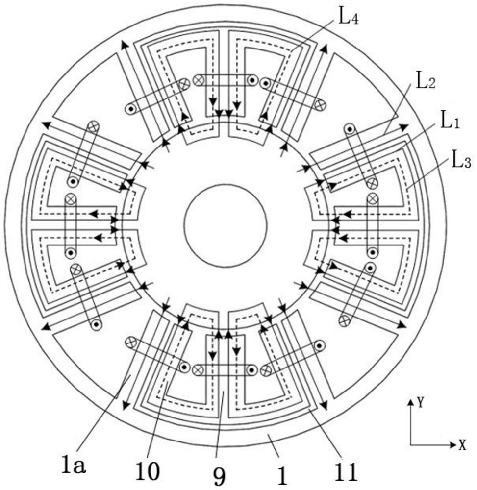
[0045]The second radial stator 2 is arranged in the first radial stator 1. Specifically, the first radial stator 1 extends radially inwards with eight first radial teeth 1a; two adjacent first radial teeth 1a Teeth 1a form an open fan-shaped slot, including 4 large slots and 4 small slots, the large slots and small slots are alternately distributed, the axis of one pair of large slots is in the horizonta...
Embodiment 2
[0063] Such as Figure 4 As shown, it is a three-dimensional structural schematic diagram of the magnetic bearing provided by the embodiment of the present invention. The structural difference from the first embodiment is that a permanent magnet 12 is provided between the first radial stator 1 and the annular magnetic permeable yoke 5, And the permanent magnet 12 is closely arranged with the first radial stator 1 and the annular magnetic yoke; the radial suspension coil 6 is wound on the first compound tooth, and the radial suspension coil 6 on the two second radial stators 2 opposite connected in series to form two radial suspension windings; the first wide tooth 9 is wound with a radial bias coil 7, and all the radial bias coils 7 are connected in series to form a radial bias winding.
[0064] The permanent magnets 12 are provided with four pieces, which are evenly distributed along the circumferential direction. The adjacent permanent magnets 12 have a space difference of 9...
Embodiment 3
[0076] Such as Figure 7 As shown, it is a three-dimensional structural schematic diagram of the magnetic bearing provided by the embodiment of the present invention. The structural difference from the second embodiment is that the permanent magnet 12 is arranged in the small groove and closely cooperates with the adjacent first narrow teeth 10. , the height of the permanent magnet 12 is smaller than the height of the first radial tooth 1 a;
[0077] The permanent magnet 12 produces a constant permanent magnet bias flux. When the radial bias winding applies DC excitation, an electromagnetic bias flux will also be generated in the magnetic bearing. By adjusting the current in the radial bias winding, The electromagnetic bias flux can be adjusted, so that the synthetic bias flux of the magnetic bearing is also adjustable; in order to avoid the magnetic circuit conflict between the permanent magnet bias flux and the electromagnetic bias flux and to enhance the two biases For the...
PUM
 Abstract
Description
Claims
Application Information
 - R&D
- Intellectual Property
- Life Sciences
- Materials
- Tech Scout
- Unparalleled Data Quality
- Higher Quality Content
- 60% Fewer Hallucinations
Browse by: Latest US Patents, China's latest patents, Technical Efficacy Thesaurus, Application Domain, Technology Topic, Popular Technical Reports.
© 2025 PatSnap. All rights reserved.Legal|Privacy policy|Modern Slavery Act Transparency Statement|Sitemap|About US| Contact US: help@patsnap.com


