
Speed reducing mechanism of hydraulic motor

A technology of deceleration mechanism and hydraulic motor, which is applied in the direction of mechanical equipment, transmission parts, friction transmission devices, etc., can solve the problems such as the inability to adjust the deceleration ratio, and achieve the effects of low cost, high speed and simple structure

Inactive Publication Date: 2019-08-16
宁波东液传动科技有限公司
View PDF9 Cites 0 Cited by
  • Summary
  • Abstract
  • Description
  • Claims
  • Application Information

AI Technical Summary

Problems solved by technology

[0002] The deceleration of hydraulic motors is generally achieved by gear transmission. The biggest problem with this deceleration mechanism is that the deceleration ratio cannot be adjusted, which cannot be satisfied for some occasions, so it is necessary to improve it.

Method used


Image

  • Speed reducing mechanism of hydraulic motor

Examples


Embodiment Construction

[0009] Below in conjunction with accompanying drawing and specific embodiment the present invention is described in further detail:

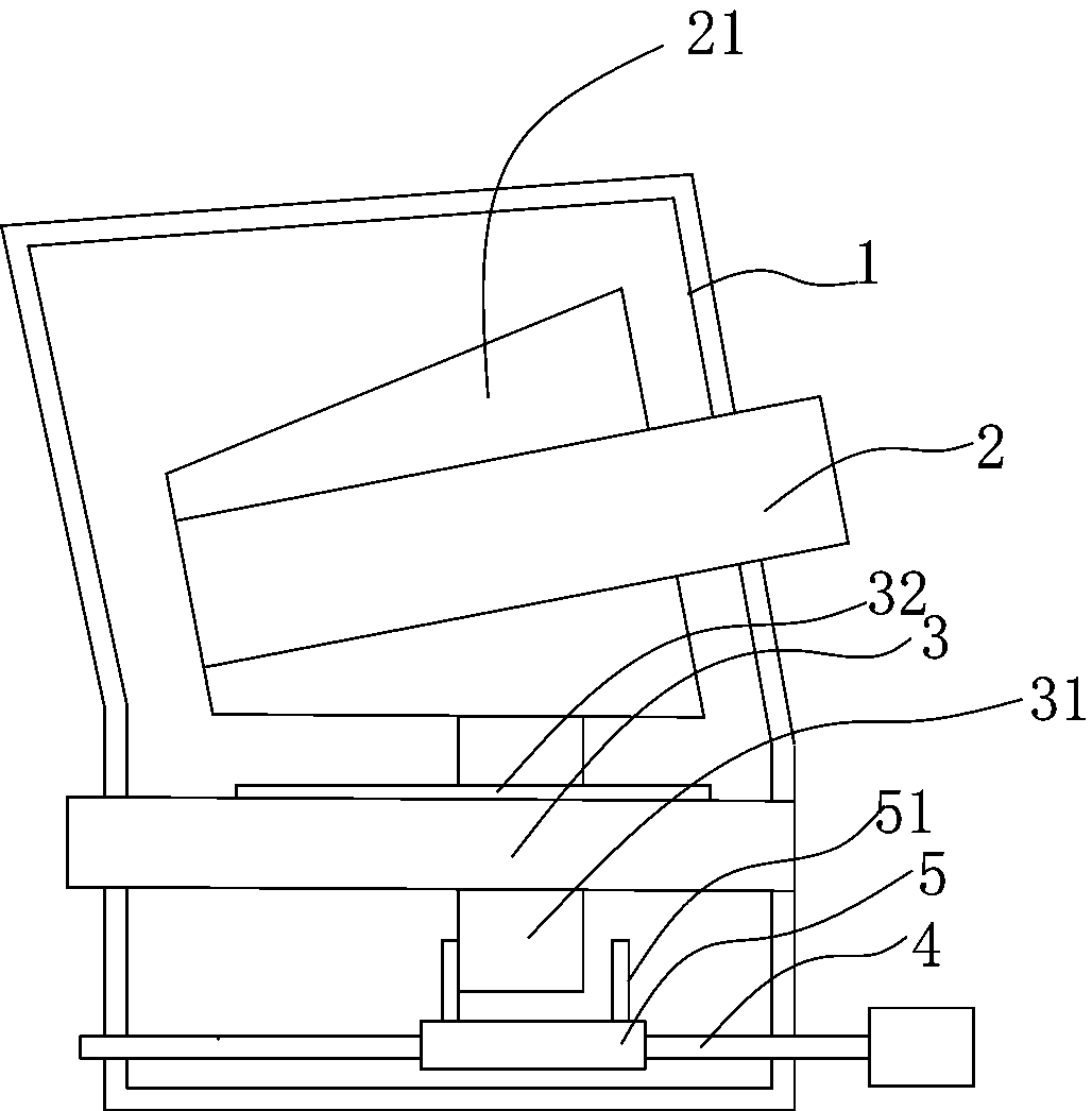
[0010] see figure 1 , the reduction mechanism of the hydraulic motor, including a box body 1, an input shaft 2 and an output shaft 3 are arranged in the box body 1, and a first friction wheel whose outer wall is a tapered surface is arranged on the input shaft 2 21. The output shaft 3 is provided with a second friction wheel 31 whose outer wall is a cylindrical surface, and a flat key 32 is provided at the connection between the second friction wheel 31 and the output shaft. The first friction wheel 21 is in close contact with the second friction wheel 31 .

[0011] The axis of the output shaft 3 is arranged parallel to the cross section of the tapered surface, the second friction wheel 31 is slidably connected to the output shaft 3, and also includes a screw 4, and the two ends of the screw 4 are rotatably connected On the box body 1, a screw...


PUM


Abstract

The invention discloses a speed reducing mechanism of a hydraulic motor. The speed reducing mechanism of the hydraulic motor comprises a box body, wherein an input shaft and an output shaft are arranged in the box body, a first friction wheel with the outer side wall being a conical surface is arranged on the input shaft, the output shaft is provided with a second friction wheel with the outer side wall being a cylindrical surface, the first friction wheel and the second friction wheel are in close contact, the axis of the output shaft is parallel to the cross section of the conical surface, the second friction wheel is slidably connected to the output shaft, the speed reducing mechanism further comprises a screw rod, two ends of the screw rod are rotationally connected to the box body, ascrew sleeve is connected to the screw rod, baffles are arranged at the two ends of the screw sleeve, the baffles are located on the two sides of the second friction wheel, and the screw sleeve is matched with the screw rod. During use, the position of the second friction wheel can be adjusted by rotating the screw rod, so that different transmission ratios are realized, the structure is simple, the cost is low, and continuous adjustment of the rotating speed can be realized.

Description

technical field [0001] The invention relates to a reduction mechanism of a hydraulic motor. Background technique [0002] The deceleration of hydraulic motors is generally achieved by gear transmission. The biggest problem with this deceleration mechanism is that the deceleration ratio cannot be adjusted, which cannot be satisfied for some occasions, so it is necessary to improve it. Contents of the invention [0003] Aiming at the deficiencies in the prior art, the present invention provides a deceleration mechanism of a hydraulic motor, which has a simple structure and can output different rotational speeds according to requirements. [0004] The present invention is achieved through the following technical solutions: the deceleration mechanism of the hydraulic motor includes a box body, and an input shaft and an output shaft are arranged in the box body, and the feature is that: the input shaft is provided with an outer wall for The first friction wheel with a conical ...

Claims


Application Information

Patent Timeline
Patent Type & Authority Applications(China)
IPC IPC(8): F16H15/44F16H57/023
CPCF16H15/44F16H57/023
Inventor 陈涉
Owner 宁波东液传动科技有限公司
Learn More