Method for controlling state of light sensor and electronic equipment

A technology of optical sensors and electronic equipment, which is applied to equipment with sensors, program control, branch equipment, etc., can solve problems such as screen flickering, achieve the effect of ensuring the signal-to-noise ratio, solving the flickering of the display area, and improving the display effect

Inactive Publication Date: 2019-08-16
HUAWEI TECH CO LTD
View PDF5 Cites 28 Cited by
  • Summary
  • Abstract
  • Description
  • Claims
  • Application Information

AI Technical Summary

Problems solved by technology

[0004] The present application provides a light sensor state control method and an electronic device, which are used to improve the screen flickering problem of the electronic device with a full screen due to the infrared light emitted by the proximity light sensor, and improve the display effect of the full screen

Method used


Image

  • Method for controlling state of light sensor and electronic equipment
  • Method for controlling state of light sensor and electronic equipment
  • Method for controlling state of light sensor and electronic equipment

Examples


Embodiment approach 1

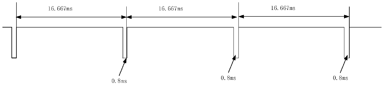
[0069] The mobile phone can monitor the control signal or pulse width modulation signal of the driver IC of the display 194. When the processor of the mobile phone detects that the control signal or the pulse width modulation signal is switched to a low level, it indicates that the light emitter near the light sensor emits infrared light. signal; when the processor of the mobile phone detects that the control signal or the pulse width modulation signal is switched to a high level, it instructs the light emitter close to the light sensor not to emit an infrared light signal.

[0070] For example, for figure 1 For the square wave of the control signal shown, when the mobile phone detects that the square wave is at a low level, it indicates that the light emitter of the proximity light sensor emits an infrared light signal; when the mobile phone detects that the square wave is at a high level, it indicates that the proximity light sensor is Optical transmitters do not emit infrar...

Embodiment approach 2

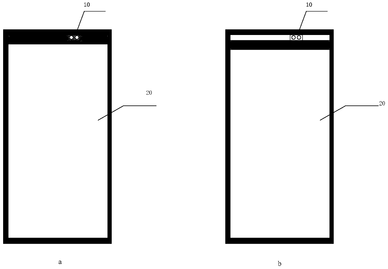
[0072] The visible light sensor can be set adjacent to the proximity light sensor. When the pixels in the display area of ​​the OLED display corresponding to the visible light sensor emit light, the visible light sensor can detect visible light, that is, monitor the display time period in the refresh cycle of the screen, and then indicate the proximity The light emitter of the light sensor does not emit an infrared light signal. When the pixels in the display area of ​​the OLED display corresponding to the visible light sensor do not emit light, the visible light sensor cannot detect visible light, that is, the non-light-emitting time period within the refresh cycle of the screen is detected, and then the light emitter close to the light sensor is instructed to start emitting infrared light light signal.

Embodiment approach 3

[0074] The mobile phone can monitor the display synchronous signal of the driver IC of the display 194. When the processor detects the display synchronous signal, it means that the display screen has just finished refreshing a frame of pictures, so the processor determines the non-light-emitting time period in the next image refresh cycle. and display a time period, indicating that the light emitter close to the light sensor emits a light signal only during the non-light-emitting time period.

[0075] It should be noted that the display screen of the mobile phone will only use PWM dimming when the brightness of the display screen is less than or equal to the set brightness value. If the brightness of the display screen is greater than the set brightness value, PWM dimming will not be used. Instead, DC dimming is used. Therefore, the embodiment of the present application is divided into the following two scenarios for description.

[0076] scene one

[0077] When the processo...


PUM


Abstract

The application provides a method for controlling the state of a light sensor and electronic equipment, and relates to the technical field of communication. The method can be applied to the electronicequipment with the light sensor under a full screen, and is used for controlling the light sensor to emit a light signal when pixels of a display area of an OLED display screen corresponding to the light sensor do not emit light in a refresh period of a picture, so that the problem of screen flicker caused by infrared light emission of the light sensor on the full screen can be solved, and the display effect of the full screen is improved. The method comprises the steps of: determining a display time period and a non-light-emitting time period in a refresh period of a picture by a processor;controlling, by the processor, a light emitter of the light sensor to emit a light signal when the pixels of the display area of the OLED display screen corresponding to the light sensor do not emit light in the refresh period of the picture; and controlling, by the processor, the light emitter to not emit a light signal when the pixels of the display area of the OLED display screen correspondingto the light sensor emit light.

Description

technical field [0001] The present application relates to the field of terminal technology, and in particular to a method for controlling the state of an optical sensor and an electronic device. Background technique [0002] In recent years, with the rapid development of the electronic industry and communication technology, there are more and more smart terminal devices, such as mobile phones, smart speakers, smart bracelets, etc., and people's lives are becoming more and more intelligent. Due to the portability of the mobile phone, and the application software of various functions can be downloaded from the application store, the mobile phone has become an indispensable must-have in people's daily life. In order to avoid accidental touches on the touch screen of the mobile phone, a proximity light sensor is usually installed near the earpiece on the top of the mobile phone. The proximity light sensor is mainly used to detect whether an object is close to a specific area of ...

Claims


Application Information

Patent Timeline
Patent Type & Authority Applications(China)
IPC IPC(8): G05B19/042G01J1/42H04M1/02G09G3/3208
CPCG05B19/042G01J1/42H04M1/026G09G3/3208H04M2250/12G09G2360/14G09G5/12G09G3/2018G09G2354/00G09G2330/027G09G2360/141H04M1/0266
Inventor 范继存康力王伟蒋淏苇李颖
Owner HUAWEI TECH CO LTD
Why Eureka
Try Eureka