Two-dimensional profile stretch bending chuck motion track design method for finite element simulation

A technology of motion trajectory and design method, applied in computing, special data processing applications, instruments, etc.

Inactive Publication Date: 2019-08-16
NORTHWESTERN POLYTECHNICAL UNIV
View PDF4 Cites 4 Cited by
  • Summary
  • Abstract
  • Description
  • Claims
  • Application Information

AI Technical Summary

Problems solved by technology

[0003] By searching the literature, it is found that the existing invention patent CN102366770A on the track design of the stretch bending chuck discloses a design method for the stretch bending loading track of a new type of stretch arm type stretch bending machine. This method is a

Method used


Image

  • Two-dimensional profile stretch bending chuck motion track design method for finite element simulation
  • Two-dimensional profile stretch bending chuck motion track design method for finite element simulation
  • Two-dimensional profile stretch bending chuck motion track design method for finite element simulation

Examples


Embodiment Construction

[0073] This embodiment is a method for designing the motion track of a two-dimensional profile stretch bending chuck for finite element simulation.

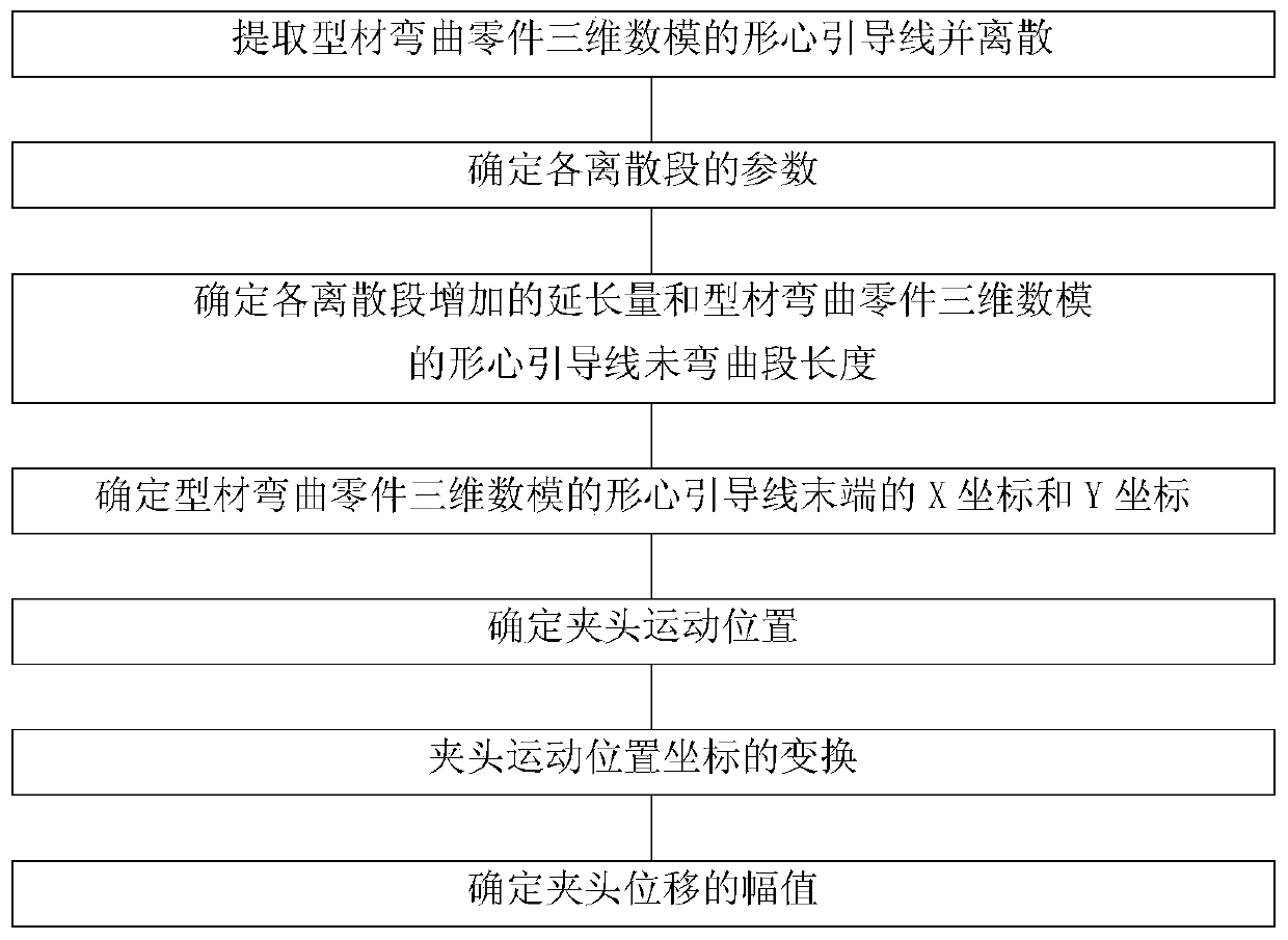
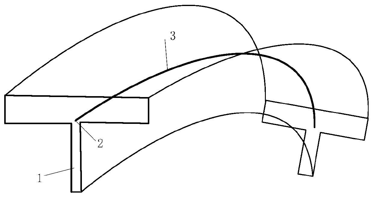
[0074] The profile bending part is a 7075-O state aluminum alloy T profile, and the length of the profile 1 is 1377mm. according to figure 1 The step-by-step design generates profile finite element simulation of the movement trajectory of the tension bending chuck. Specifically include the following steps:

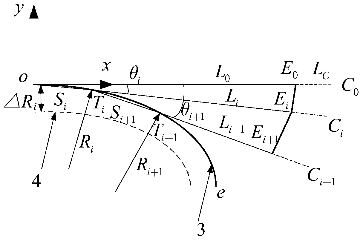
[0075] Step 1: Extract and discretize the centroid guideline of the 3D digital model of the profile bending part.

[0076] Extract the centroid guide line of the 3D digital model of the curved part of the profile:

[0077] The 3D digital model of the profile bending part is obtained according to the size of the part, in CATIA from the geometric size of the part section and a guide line through sweeping, and the centroid guideline 3 of the 3D digital model of the profile bending part is extracted.

[0078] The centroid po...


PUM


Abstract

The invention discloses a two-dimensional profile stretch bending chuck motion track design method for finite element simulation. In order to solve the problem of determination of displacement boundary conditions in the sectional material stretch bending forming finite element simulation process, the method comprises the following steps: establishing a chuck motion track calculation method based on an end face centroid coupling control point, combining the chuck motion track calculation method in the bending process with a finite element simulation displacement boundary condition definition method, and obtaining the chuck motion track in the finite element simulation process according to different pre-tensioning amounts and strain neutral layer inward shifting amounts. According to the invention, the defects in the design of the motion trail of the traditional equal-curvature two-dimensional profile stretch bending chuck are overcome; the method adapts to the stretch bending parametersof three aspects of pre-stretching amount, neutral layer inward movement amount and complementary stretching amount in the stretch bending process, the stretch bending chuck movement track can be quickly calculated, the finite element simulation stretch bending chuck movement track boundary condition definition is smoothly completed, and the simulation result shows that the chuck movement track design method is accurate and reliable.

Description

technical field [0001] The invention relates to a finite element simulation technology for two-dimensional profile stretch-bending forming, in particular to a motion track design method for a two-dimensional profile stretch-bending chuck used for finite element simulation. Background technique [0002] As an important profile bending process, stretch bending has the advantages of small springback and good quality, and is widely used in aircraft, rocket, high-speed rail, automobile manufacturing and construction industries. The principle of stretch bending forming is that a tangential force is applied to the metal profile while bending, and the section is in a state of tensile stress, and the stress is uniform, so that the rebound after forming is small. Stretch bending process parameters include the amount of pre-stretching, the amount of inward movement of the strain neutral layer during the bending process, the amount of supplementary stretching, etc. These parameters dire...

Claims


Application Information

Patent Timeline
IPC IPC(8): G06F17/50
CPCG06F30/23G06F30/17
Inventor 王安洋王永军仝朋艳刘辉闾家阳孙兴顾锐
Owner NORTHWESTERN POLYTECHNICAL UNIV
Why Eureka
Try Eureka