

Protective element with grid inside insulating tube
A technology of protection element and insulating tube, applied in the field of protection element with fusing function, can solve the problem of difficulty in further improving the breaking capacity of the protection element, and achieve the effect of improving the breaking capacity and improving the arc extinguishing effect.
- Summary
- Abstract
- Description
- Claims
- Application Information
AI Technical Summary
Problems solved by technology
Method used
Image

Examples
Embodiment 1
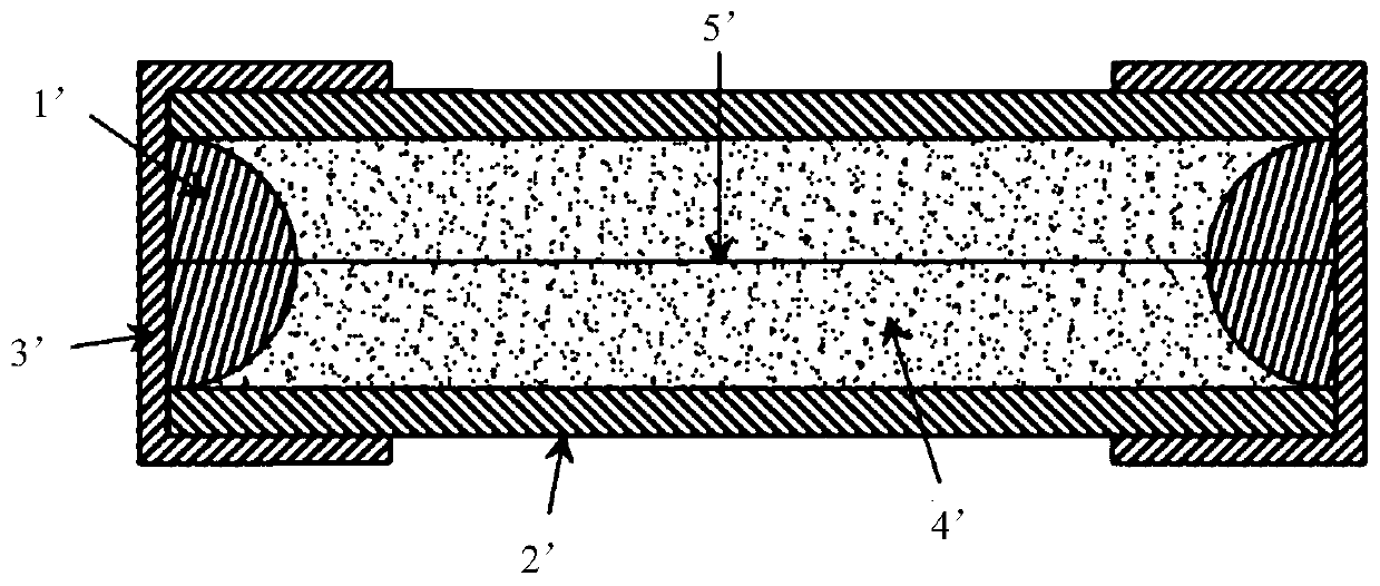
[0032] like figure 2 and image 3 As shown, the protection element in this embodiment, especially a miniature protection element, includes solder 1, an insulating tube 2, an electrode 3, an arc extinguishing material 4, a double melt 5-1 / 5-2, and a A plate-shaped grid 6 . The grid 6 in the insulating tube can be made of ceramic material or insulating material such as PCB; it can be formed together with the insulating tube 2, or it can be separately formed and placed into the insulating tube. The insulating tube 2 is tubular, with a square or round shape, and a grid 6 and a receiving cavity formed therein; the electrode 3 is a matching conductive metal cap sleeved on it, which is arranged at both ends of the insulating tube 2, and the double melt 5 The two ends of the -1 / 5-2 are fixed in the middle of the two end electrodes 3 by the solder 1 and form an electrical connection with the two end electrodes 3. The double melt 5-1 / 5-2 is arranged in the arc extinguishing material ...
Embodiment 2
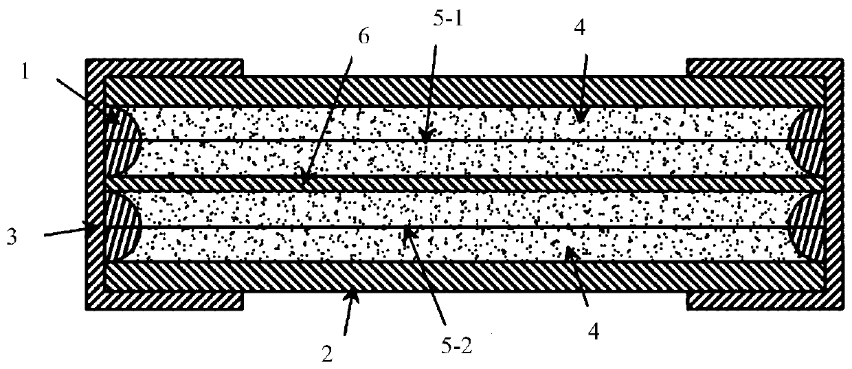
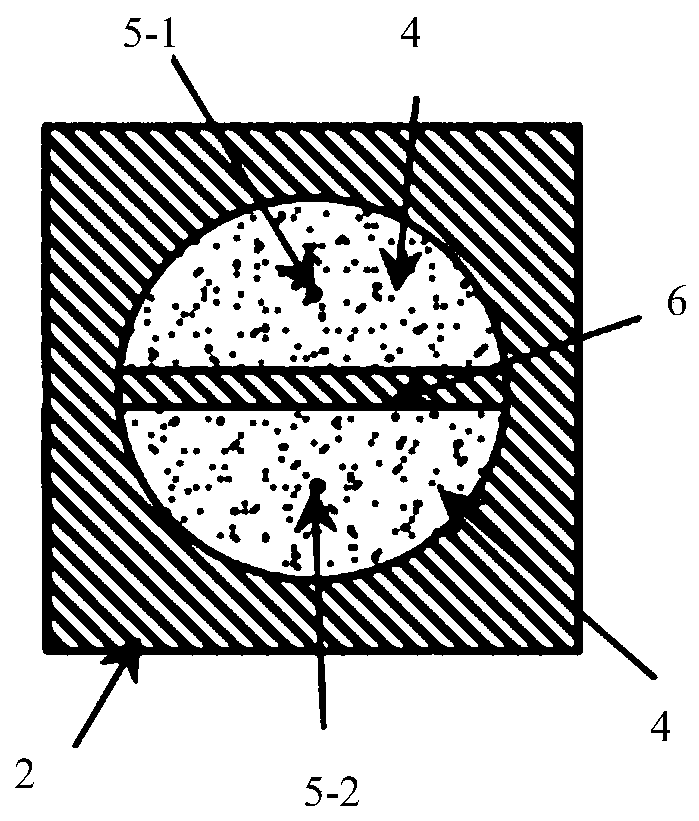
[0035] like Figure 4 and Figure 5 As shown, a protection element, especially a miniature protection element, comprises solder 1, insulating tube 2, electrode 3, arc extinguishing material 4, internal melt 5-1 / 5-2 / 5-3 / 5-4, insulation There are two grids 6 inside the tube, and the two grids cross each other, and the cross section is "cross" shape. The insulating tube 2 is tubular, with a square or circular shape, and the internal grid 6 forms four independent accommodating cavities, and each accommodating cavity is provided with a melt. The electrode 3 is a matching conductive metal cap sleeved on it, which is arranged on both ends of the insulating tube 2, and the two ends of the inner melt 5-1 / 5-2 / 5-3 / 5-4 are fixed to the electrodes at both ends by the solder 1 3 in the middle and form an electrical connection with the electrodes 3 at both ends, and the internal melt 5-1 / 5-2 / 5-3 / 5-4 is arranged in the arc extinguishing material 4 .
[0036] further. When the breaking cur...
Embodiment 3
[0038] like Image 6 and Figure 7 As shown, a protective element, especially a miniature protective element, includes solder 1, insulating tube 2, electrode 3, arc extinguishing material 4, internal melt 5-1 / 5-2 / 5-3, and two inner layers of insulating tube Grid 6, the two grids do not intersect each other. The insulating tube 2 is tubular, square or round in shape, and has two plate-shaped grids 6 inside to form three independent storage cavities, and each storage cavity is correspondingly provided with a melt. The electrode 3 is a matching conductive metal cap set on it, which is arranged at both ends of the insulating tube 2, and the two ends of the internal melt 5-1 / 5-2 / 5-3 are fixed in the middle of the electrodes 3 at both ends by solder 1 and connected to the The electrodes 3 at both ends form an electrical connection, and the internal melt 5-1 / 5-2 / 5-3 / is arranged in the arc-extinguishing material 4 .
[0039] When the breaking current arrives, the internal fuses 5-...
PUM
 Abstract
Description
Claims
Application Information