Linear motor structure for telescopic sliding door

A linear motor and sliding door technology, applied in the direction of power control mechanism, leaf control mechanism, electrical components, etc., can solve the problems of not having a variety of door frame widths, various types, and high cost

Pending Publication Date: 2019-08-16
ZHONGSHAN OPIKE HARDWARE PROD CO LTD
View PDF12 Cites 1 Cited by
  • Summary
  • Abstract
  • Description
  • Claims
  • Application Information

AI Technical Summary

Problems solved by technology

In the prior art, the mover assembly is usually non-adjustable. Once it is determined, it can only be applied to the door frame of a specific width, and for other door frames with different widths, only the corresponding mover can be reproduced. Components, that is to say, the applicable occasions of the mover components in the prior art are fixed, and they do not have the ability to adapt to various door frame widths. Design a moving subassembly of one specification, resulting in disadvantages such as a wide variety and high cost

Method used


Image

  • Linear motor structure for telescopic sliding door
  • Linear motor structure for telescopic sliding door
  • Linear motor structure for telescopic sliding door

Examples


Embodiment Construction

[0041] The following will clearly and completely describe the technical solutions in the embodiments of the present invention with reference to the accompanying drawings in the embodiments of the present invention. Obviously, the described embodiments are only part of the embodiments of the present invention, not all of them. Based on the embodiments of the present invention, all other embodiments obtained by persons of ordinary skill in the art without creative efforts fall within the protection scope of the present invention.

[0042] It should be noted that all directional indications (such as up, down, left, right, front, back, outside, inside...) in the embodiments of the present invention are only used to explain the direction of movement in a certain posture (as shown in the accompanying drawing). The relative positional relationship between the various components, the movement conditions, etc., if the specific posture changes, the directional indication will also change...


PUM


Abstract

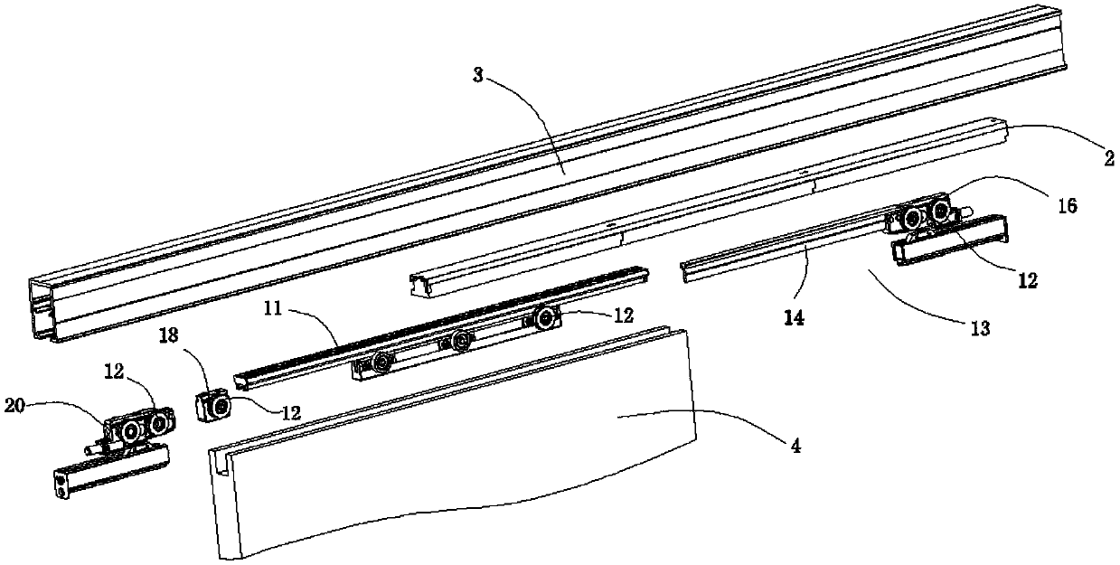
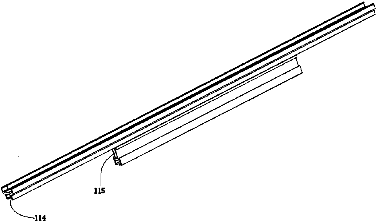
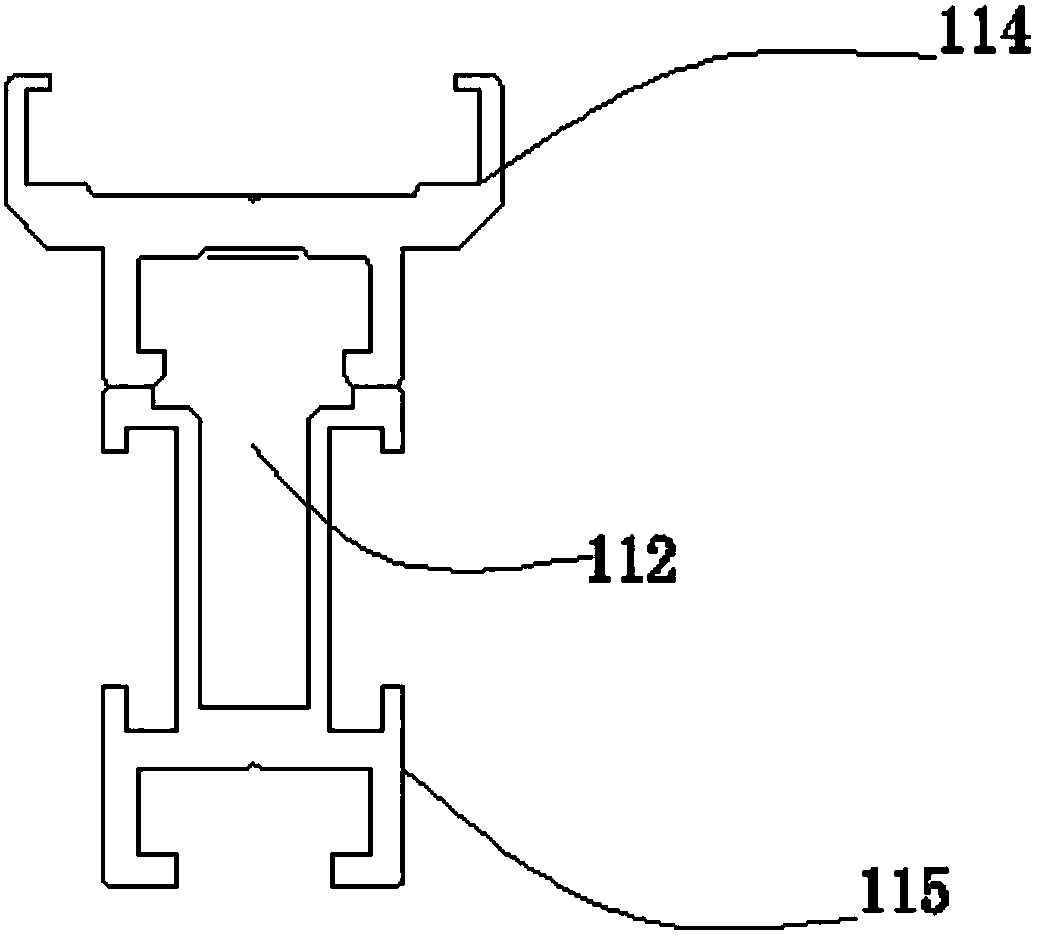
The invention relates to a linear motor structure for a telescopic sliding door. The linear motor structure comprises a mover module comprising a fixing portion and a movable portion, wherein the fixing portion comprises a permanent magnet, the lower portion of the permanent magnet is provided with slotted hole, the movable portion comprises a telescopic rod which can be slidingly inserted from one end of the slotted hole and a movement output portion configured to output the motion of the mover module, and the movable portion and the fixing portion are fixed through a fastening piece. The linear motor structure is novel in design and reasonable in design, can flexibly regulate the length of the mover module according to the width of the door frame, and is good in adaptability.

Description

technical field [0001] The invention relates to a linear motor structure, in particular to a retractable linear motor structure for a sliding door. Background technique [0002] A linear motor usually includes a stator assembly and a mover assembly, the stator assembly is installed and fixed above the track, and the mover assembly has a permanent magnet, which is installed in parallel below the stator assembly and has a certain gap with the stator assembly. When working, the current in the stator assembly is changed through the controller. Due to the principle of electromagnetic induction, it will be able to drive the mover assembly equipped with permanent magnets to slide left and right in the track, and then connect the mover assembly with the door body to transmit its motion to The door body can realize the opening and closing of the door body. In the prior art, the mover assembly is usually non-adjustable. Once it is determined, it can only be applied to the door frame ...

Claims


Application Information

Patent Timeline
Patent Type & Authority Applications(China)
IPC IPC(8): H02K41/03E05F15/632
CPCH02K41/031E05F15/632E05Y2900/132
Inventor 许姜德
Owner ZHONGSHAN OPIKE HARDWARE PROD CO LTD
Why Eureka
Try Eureka