Machine room chute

A technology for cable racks and machine rooms, which is applied in the direction of pipe supports, mechanical equipment, electrical components, etc., which can solve the problems of scratches and bruises on the coating, heavy weight, and affect the appearance, and achieve convenient installation, large carrying capacity, and reduced difficulty Effect

Inactive Publication Date: 2008-08-27
SUS TELECOMM
View PDF0 Cites 5 Cited by
  • Summary
  • Abstract
  • Description
  • Claims
  • Application Information

AI Technical Summary

Problems solved by technology

[0002] At present, the cable racks used in the machine room on the market are made of porous U-shaped steel, angle steel, flat steel, cold-rolled plate and other materials, which are heavy and inconvenient to use; Insufficient, the coating is easily scratched and damaged in the process of production, transportation and installation, resulting in paint loss, zinc loss, etc., which seriously affects the appearance, and the existing combined cable racks made of section steel, angle steel, cold-rolled plate and other materials , the connection mode of the beams, vertical beams, vertical beams and suspensions is plug-in connection with holes, the production process is complicated, and the installation is not flexible enough, which increases the difficulty of installation

Method used


Image

  • Machine room chute
  • Machine room chute
  • Machine room chute

Examples


Embodiment Construction

[0046] The present invention will be described in further detail below in conjunction with accompanying drawing:

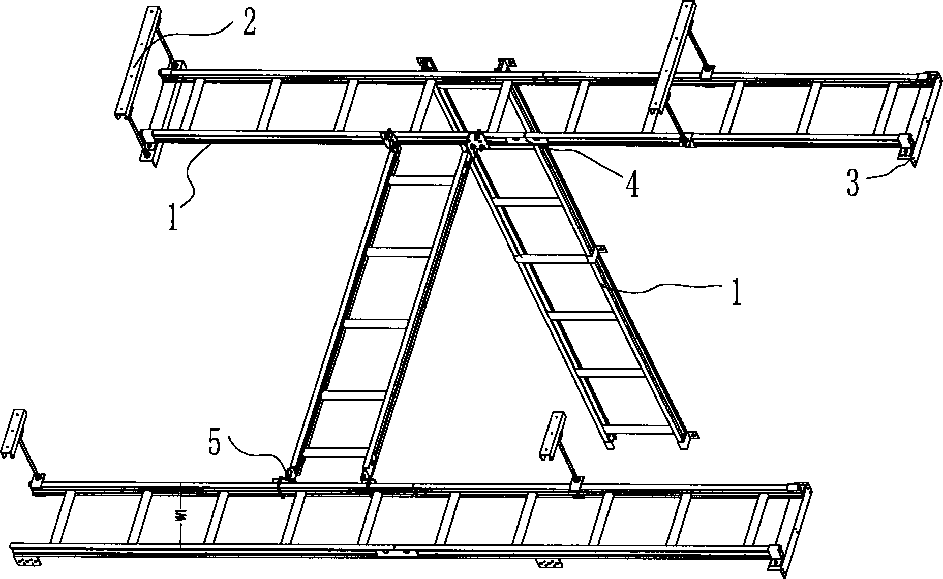
[0047] see figure 1 As shown, the cabling rack in the machine room is made of a wire rack 1 made of aluminum profiles; It is composed of a straight connecting plate 4 for horizontal connection between one wire frame and a corner connection component 5 for vertical connection between two wire frames. The cable tray made of aluminum profile is easy to process and can be cut according to the required length.

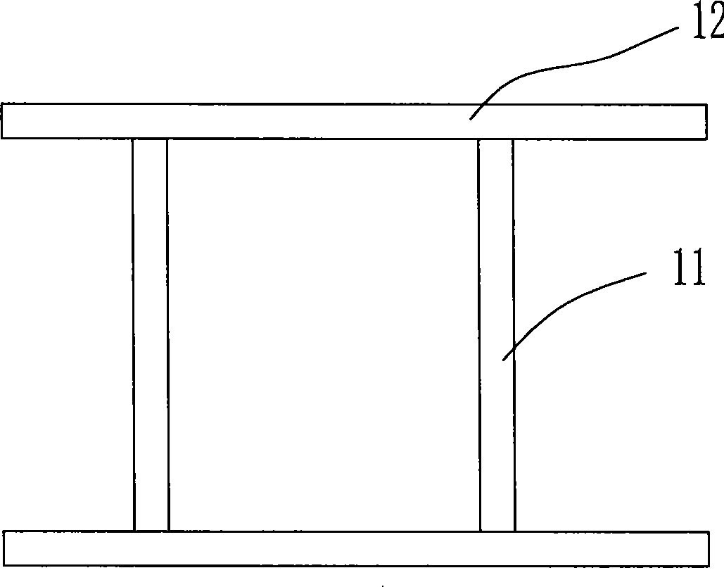
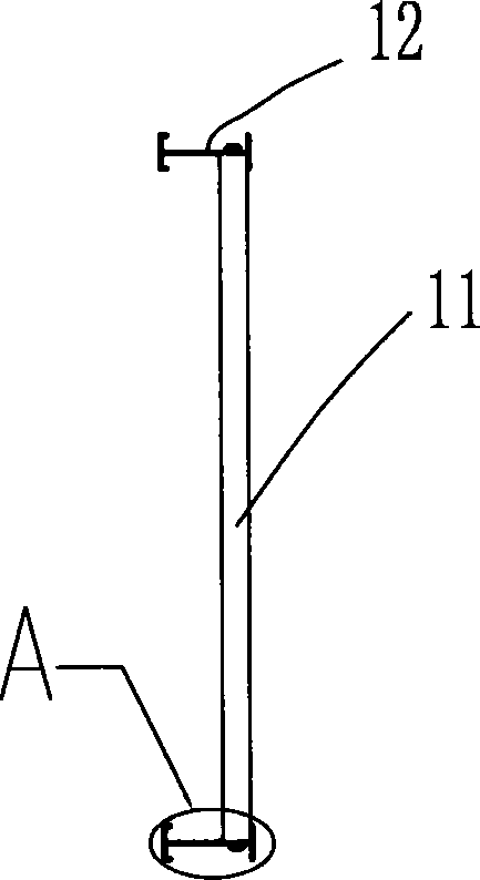
[0048] see figure 2 , image 3 , Figure 4 , Figure 5 , Figure 6 As shown, the wire frame 1 is composed of a central beam 11 and a main beam 12 vertically fixed by self-tapping screws 13 at both ends thereof.

[0049] The main girder 12 consists of a section bar 121 in an H-shaped frame, an E-shaped frame 1211 whose two ends of a longitudinal side protrude inward and are parallel to the horizontal side, and a straight line between the middle beam 11 a...


PUM


Abstract

The invention relates to a room cable trough, in particular to an aluminium cable trough with the surface oxidized, which is used in a cable room to arrange cables and optical cables on terminal equipment and to slidingly and flexibly connect the cable troughs inside and outside a base station and is capable of improving production efficiency and reducing installation difficulty. The cable trough is composed of a cable holder, a suspender subassembly which is hitched on the cable holder and can be adjusted longitudinally, wall support subassemblies respectively arranged at two ends of the cable holder, a direct connecting board which is transversely connected between two cable holders if necessary and a corner connecting subassembly longitudinally connected between two cable holders.

Description

technical field [0001] The present invention relates to a kind of equipment specially used for wire routing in a computer room, in particular to a wire rack in a computer room for laying cables inside and outside a base station by laying cables and optical cables directly into terminal equipment after entering a telecommunication operation computer room. Background technique [0002] At present, the cable racks used in the machine room on the market are made of porous U-shaped steel, angle steel, flat steel, cold-rolled plate and other materials, which are heavy and inconvenient to use; Insufficient, the coating is easily scratched and damaged in the process of production, transportation and installation, resulting in paint loss, zinc loss, etc., which seriously affects the appearance, and the existing combined cable racks made of section steel, angle steel, cold-rolled plate and other materials , the connection mode of the beams, vertical beams, vertical beams and suspensio...

Claims


Application Information

Patent Timeline
Patent Type & Authority Applications(China)
IPC IPC(8): H02G3/02H02G3/30F16L3/00
Inventor 阮连发杨庆华华荣姜廷宇霍文权林鸿彬简计恩
Owner SUS TELECOMM
Why Eureka
Try Eureka