Network domain partitioning method for reducing end-to-end time delay of optical transport network

An optical transport network and delay technology, applied in the field of optical communication, can solve the problems of increased end-to-end transmission delay, service detours, etc., so as to reduce the end-to-end delay of services, ensure low delay, and improve network time. The effect of extension

Active Publication Date: 2019-08-16
BEIJING UNIV OF POSTS & TELECOMM
View PDF2 Cites 2 Cited by
  • Summary
  • Abstract
  • Description
  • Claims
  • Application Information

AI Technical Summary

Problems solved by technology

When the division of network areas and the selection of central nodes are unreasonable, problems such as business detours will be caused, which will increase the end-to-end transmission delay
Traditional communicatio

Method used


Image

  • Network domain partitioning method for reducing end-to-end time delay of optical transport network
  • Network domain partitioning method for reducing end-to-end time delay of optical transport network
  • Network domain partitioning method for reducing end-to-end time delay of optical transport network

Examples


Embodiment 1

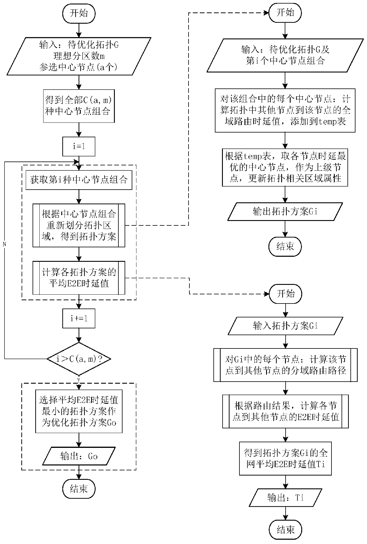
[0104] Take the six-node topology as an example for illustration, such as Figure 4 As shown, assuming that all nodes in the network can be used as central nodes, the network is divided into two areas, and the specific steps are as follows:

[0105] 1. Input the six-node topology as the topology G to be optimized, the ideal number of partitions m=2, and the set of participating central nodes N={n 1 ,n 2 ,n 3 ,n 4 ,n 5 ,n 6}.

[0106] 2. According to the topology G to be optimized, the number of ideal partitions m and the set N of participating central nodes, all the common A combination of central nodes.

[0107] Among them, each central node combination contains two central nodes in the central node set N, which are:

[0108] C 1 =(n 1 ,n 2 ),C 2 =(n 1 ,n 3 ),C 3 =(n 1 ,n 4 ),C 4 =(n 1 ,n 5 ),C 5 =(n 1 ,n 6 ),C 6 =(n 2 ,n 3 ),C 7 = (n 2 ,n 4 ),C 8 =(n 2 ,n 5 ),C 9 =(n 2 ,n 6 ),C 10 =(n 3 ,n 4 ),C 11 =(n 3 ,n 5 ),C 12 =(n 3 ,n 6 ),C...

Embodiment 2

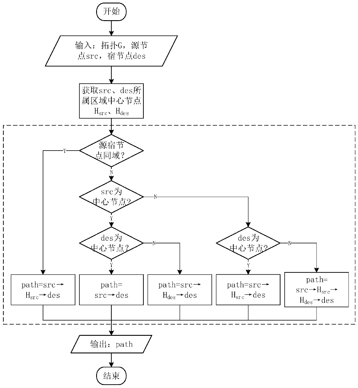
[0133] Such as Figure 5 As shown, the six-node topology G has been divided into regions, and the node pairs (n 3 ,n 4 ),(n 5 ,n 6 ),(n 5 ,n 1 ),(n 3 ,n 6 ),(n 4 ,n 1 ) between domain-specific routing paths.

[0134] (A) source node src=n 3 , sink node des=n 4

[0135] 1. Input the topology G of the divided area, source node src=n 3 , sink node des=n 4 ;

[0136] 2. According to the area division of G, the central nodes of the source and sink nodes are respectively H src =n 5 、H des =n 5 ;

[0137] 3. According to the area division of G, it can be seen that the source and sink nodes belong to area1, so use the D algorithm to calculate src→H des → des, can get path=[n 3 ,n 5 ,n 4 ].

[0138] (B) source node src=n 5 , sink node des=n 6

[0139] 1. Input the topology G of the divided area, source node src=n 5 , sink node des=n 6 ;

[0140] 2. According to the area division of G, the central nodes of the source and sink nodes are respectively H src =...

Embodiment 3

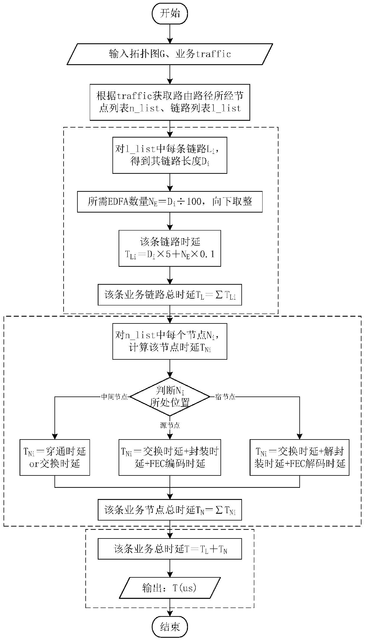
[0155] Such as Figure 5 As shown, the six-node topology G has been divided into areas, and the known service routing path P=[n 4 ,n 5 ,n 6 ,n 1 ], assuming that the service bandwidth B=1000MHz, calculate the node pair (n 4 ,n 1 ) service end-to-end delay. For the convenience of description, it is assumed that the nodes in the topology are all 100Gbps OTN equipment, and the intermediate nodes adopt optical layer scheduling. Specific steps are as follows:

[0156] 1. Input topology G, business traffic=(B,P)=(1000MHz,[n 4 ,n 5 ,n 6 ,n 1 ]);

[0157] 2. Obtain the node set n that the business passes through list ={n 4 ,n 5 ,n 6 ,n 1}, link set l list ={(n 4 ,n 5 ),(n 5 ,n 6 ),(n 6 ,n 1 )};

[0158] 3. According to l list Calculate the link delay of the service:

[0159]

[0160] That is, the total end-to-end link delay T of this service l =1750.1us.

[0161] 4. According to n list Calculate the node delay of the service:

[0162] node ...


PUM


Abstract

The invention discloses a network domain partitioning method for reducing the end-to-end time delay of an optical transmission network, and belongs to the technical field of optical communication. Themethod comprises the steps of firstly inputting a to-be-optimized topology, an ideal partition number m and a selected node set N; selecting m nodes from the set N to construct a node combination; secondly, re-dividing a topological area for each node combination to obtain a respective corresponding topological scheme; calculating an average end-to-end time delay value of each combined and updated topological scheme; and finally, selecting the topology scheme with the minimum average end-to-end time delay value as the sub-domain topology scheme with the optimal time delay. Through the reasonable network planning, the service detour can be avoided when the service end-to-end transmission is carried out, the link time delay is reduced, the node time delay is reduced, the network time delayperformance is improved, and the requirement for low-time-delay and time-delay sensitive services can be better met.

Description

technical field [0001] The invention belongs to the technical field of optical communication, relates to optical transmission network technology, in particular to a network domain division method for reducing end-to-end time delay of the optical transmission network. Background technique [0002] With the development of communication technology and the popularization of Internet applications, some industries and services have put forward extremely strict requirements on network delay performance, and network delay performance has gradually become one of the emerging hotspots in the communication field. Optical Transport Network (OTN) technology is based on Wavelength Division Multiplexing (WDM) technology, and integrates the electrical layer processing and network management capabilities of Synchronous Digital Hierarchy (SDH) technology, and has the advantages of flexible service scheduling and large-capacity transmission; in addition, Due to the low service level and rigid ...

Claims


Application Information

Patent Timeline
IPC IPC(8): H04Q11/00
CPCH04Q11/0067H04Q2011/0073H04Q2011/0083
Inventor 李慧王文雯占天顺纪越峰
Owner BEIJING UNIV OF POSTS & TELECOMM
Why Eureka
Try Eureka