Systems and methods for head-mounted display adapted to human visual mechanism

A head-mounted display, display technology, applied in stereo systems, static indicators, cathode ray tube indicators, etc., can solve the problems of reducing the density of photoreceptors and low resolution

Inactive Publication Date: 2019-08-16
MOVIDIUS LTD
View PDF7 Cites 2 Cited by
  • Summary
  • Abstract
  • Description
  • Claims
  • Application Information

AI Technical Summary

Problems solved by technology

The remainder of the retina provides lower resolution and reduced photoreceptor density

Method used


Image

  • Systems and methods for head-mounted display adapted to human visual mechanism
  • Systems and methods for head-mounted display adapted to human visual mechanism
  • Systems and methods for head-mounted display adapted to human visual mechanism

Examples


Embodiment Construction

[0028]In the following description, numerous specific details are set forth regarding the systems and methods of the disclosed subject matter, the environments in which these systems and methods may operate, etc., in order to provide a thorough understanding of the disclosed subject matter. However, it will be apparent to those skilled in the art that the disclosed subject matter may be practiced without these specific details and certain features that are known in the art have not been described in detail to avoid obscuring the disclosed subject matter. Additionally, it should be understood that the examples provided below are exemplary and it is contemplated that there are other systems and methods that fall within the scope of the disclosed subject matter.

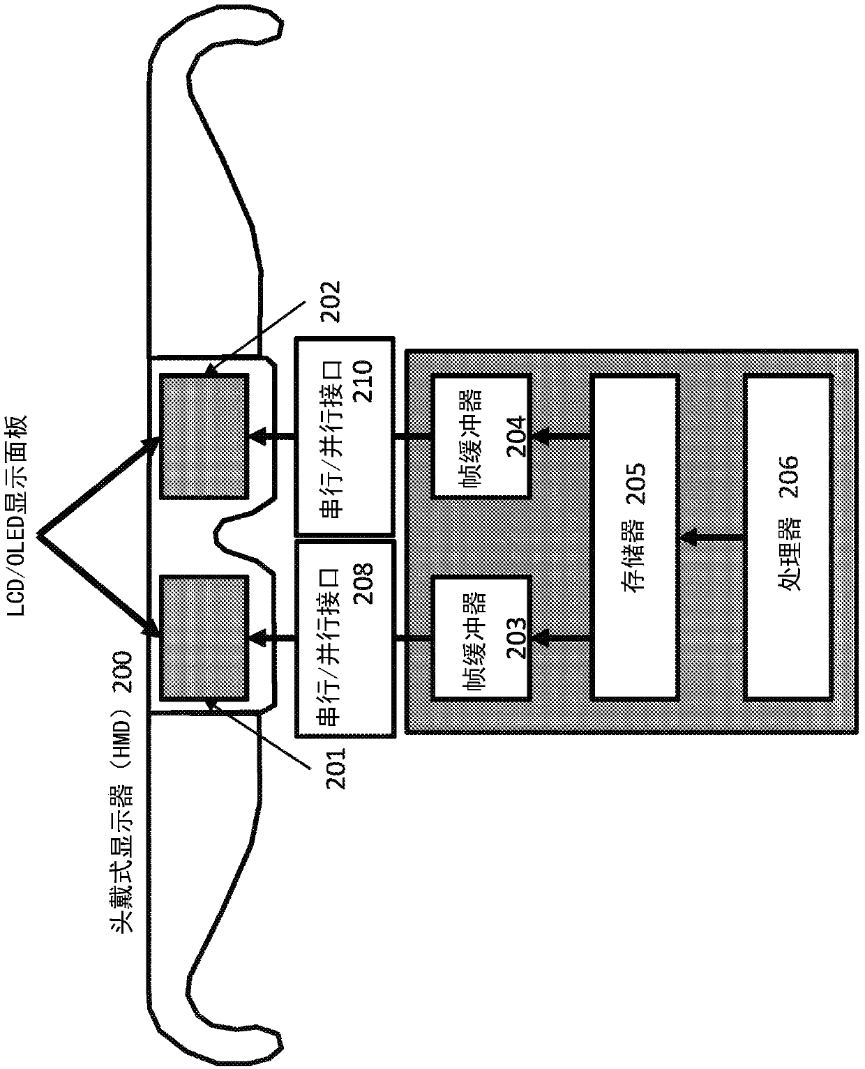
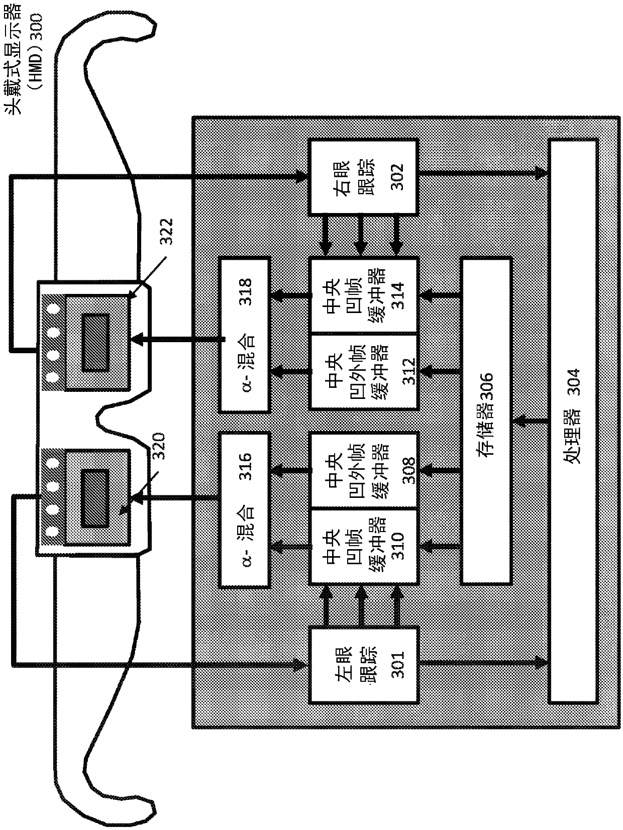
[0029] The present invention utilizes a head mounted display with eye tracking. A display panel backed by a framebuffer is used to render each pixel in the output frame. Eye / pupil movement and / or position are measured ...


PUM


Abstract

Systems and methods are provided for rendering of a dual eye-specific display. The system tracks the user's eye movements and / or positions, in some implementations, based on electroencephalography (EEG) of the user, to correctly label the central (foveal) and peripheral (extra-foveal) areas of the display. Foveal data is fully rendered while extra-foveal data is reduced in resolution and, in someimplementations, shared between the two displays.

Description

technical field [0001] The present application relates generally to computer vision processing, and more specifically, to efficient image simulation in head-mounted displays. Background technique [0002] Continuing advances in the speed and acuity of computers, particularly those associated with graphics hardware and software, have recently created, indeed, decades-long aspirations for immersive computer-generated environments. Virtual reality devices with body tracking, haptic feedback and head-mounted sensing devices are now being developed for consumer use. Demand for graphics systems remains strong as cutting-edge systems attempt to deliver more impressive and realistic artificial environments. Additionally, efficient rendering and display in both hardware and software remains critical. [0003] Advances in computer graphics and imaging technology have resulted in a new generation of head-mounted display devices, the intent of which is to provide users with the most r...

Claims


Application Information

Patent Timeline
IPC IPC(8): H04N13/344H04N13/383H04N13/398G02B27/01G02B27/00H04N19/597H04N19/132H04N19/17H04N19/167H04N19/426
CPCH04N19/597H04N19/132H04N19/17H04N19/167H04N19/426H04N13/344H04N13/383H04N13/398G02B27/0093G02B27/017G02B2027/0132G02B2027/014G06V40/18G06F3/013G09G5/006G09G5/391G09G2340/0407G09G2354/00G09G2360/18
Inventor D·莫洛尼B·巴里
Owner MOVIDIUS LTD
Why Eureka
Try Eureka