Lumbar cistern drainage and intracranial pressure monitoring system

A monitoring system and intracranial pressure technology, applied in the direction of pumping and pumping system, spinal fluid pressure measurement, suction equipment, etc., to achieve the effect of avoiding backflow

Pending Publication Date: 2019-08-20
刘海波
View PDF0 Cites 2 Cited by
  • Summary
  • Abstract
  • Description
  • Claims
  • Application Information

AI Technical Summary

Benefits of technology

This technology helps monitor blood pressures inside your head while draining fluids from it. It uses an external device called a system that controls how much liquid flows out when there's no more than two inches or five pounds per square centimeter (cm2). When this happens, certain parts will be blocked off due to gravity causing backward movement within the body. These devices prevent any harmful substances from entering our brains without being able to get them down properly.

Problems solved by technology

This patented technical problem addressed in this patents relates to measuring intra-cranial pressures during medical procedures such as lumber spine surgeries with continuous drainages (CDI) which may cause excessive blood loss due to bleeding from damaged brain tissue around them. Existing methods involve inserting probes inside the body via incision, but these techniques have limitations when it comes across necrotic areas near nerves where they might be harmful if inserted too much deeper than usual.

Method used


Image

  • Lumbar cistern drainage and intracranial pressure monitoring system
  • Lumbar cistern drainage and intracranial pressure monitoring system
  • Lumbar cistern drainage and intracranial pressure monitoring system

Examples


Embodiment 1

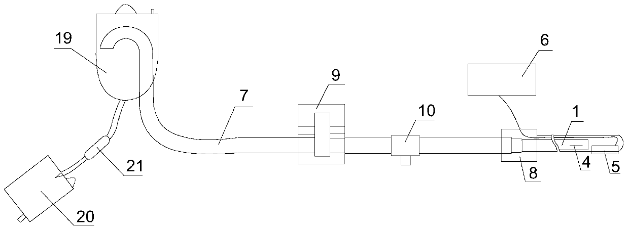
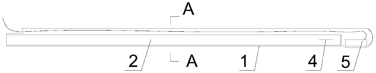
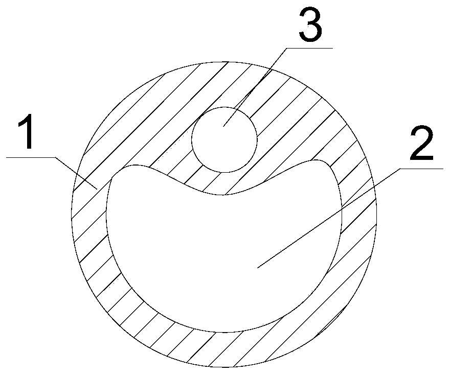
[0030] Such as Figure 1-3 As shown, a lumbar cistern drainage and intracranial pressure monitoring system includes a drainage tube 1 that is a flexible tube. The drainage tube 1 is provided with a cerebrospinal fluid flow channel 2 and a wire channel 3. One end of the cerebrospinal fluid flow channel 2 is closed, and the wire channel The length of 3 is less than the length of cerebrospinal fluid channel 2. The side wall of the insertion end of the drainage tube 1 is provided with a drainage port 4 communicating with the cerebrospinal fluid channel 2 (the drainage port 4 is a long strip opening or a plurality of small round holes), and the insertion end of the drainage tube 1 A pressure sensor 5 is provided, and the pressure sensor 5 is embedded in the insertion end of the drainage tube 1 , and the sensing surface of the pressure sensor 5 is exposed, that is, the sensing surface protrudes from the side wall of the drainage tube 1 . The drainage tube 1 is provided with a scale...

Embodiment 2

[0034] Such as Figure 1-3 As shown, a lumbar cistern drainage and intracranial pressure monitoring system includes a drainage tube 1 that is a flexible tube. The drainage tube 1 is provided with a cerebrospinal fluid flow channel 2 and a wire channel 3. One end of the cerebrospinal fluid flow channel 2 is closed, and the wire channel The length of 3 is less than the length of cerebrospinal fluid channel 2. The side wall of the insertion end of the drainage tube 1 is provided with a drainage port 4 communicating with the cerebrospinal fluid channel 2 (the drainage port 4 is a long strip opening or a plurality of small round holes), and the insertion end of the drainage tube 1 A pressure sensor 5 is provided, and the pressure sensor 5 is embedded in the insertion end of the drainage tube 1 , and the sensing surface of the pressure sensor 5 is exposed, that is, the sensing surface protrudes from the side wall of the drainage tube 1 . The drainage tube 1 is provided with a scale...

Embodiment 3

[0040] Such as Figure 1-3 As shown, a lumbar cistern drainage and intracranial pressure monitoring system includes a drainage tube 1 that is a flexible tube. The drainage tube 1 is provided with a cerebrospinal fluid flow channel 2 and a wire channel 3. One end of the cerebrospinal fluid flow channel 2 is closed, and the wire channel The length of 3 is less than the length of cerebrospinal fluid channel 2. The side wall of the insertion end of the drainage tube 1 is provided with a drainage port 4 communicating with the cerebrospinal fluid channel 2 (the drainage port 4 is a long strip opening or a plurality of small round holes), and the insertion end of the drainage tube 1 A pressure sensor 5 is provided, and the pressure sensor 5 is embedded in the insertion end of the drainage tube 1 , and the sensing surface of the pressure sensor 5 is exposed, that is, the sensing surface protrudes from the side wall of the drainage tube 1 . The drainage tube 1 is provided with a scale...


PUM


Abstract

The invention belongs to the technical field of medical equipment, and discloses a lumbar cistern drainage and intracranial pressure monitoring system. The system comprises a drainage tube (1), wherein a cerebrospinal fluid flowing channel (2) and a wire channel (3) are arranged on the drainage tube (1); a drainage hole (4) which communicates with the cerebrospinal fluid flowing channel (2) is formed in an insert-in end part of the drainage tube (1); a pressure sensor (5) is arranged on the insert-in end part of the drainage tube (1); the drainage tube (1) communicates with a connecting pipe (7) through an adapter (8); a flow controller (9) is arranged on the connecting pipe (7); and a backward-flow prevention structure is arranged at the tail end of the connecting pipe (7). According to the lumbar cistern drainage and intracranial pressure monitoring system disclosed by the invention, the change of intracranial pressure can be monitored, the drainage speed and the drainage volume of the cerebrospinal fluid can be controlled, and the backward-flow of the cerebrospinal fluid is avoided; and meanwhile, the risks of cerebral hernia caused by excessive amount of the drainage and over-high speed of the drainage during puncturing are avoided, and observation of the smoothness of the drainage of the cerebrospinal fluid is facilitated.

Description


Claims


Application Information

Patent Timeline
Owner 刘海波
Why Eureka
Try Eureka