Accurate positioning machine suitable for high-frequency ultrasound probe and control method

An ultrasonic probe and precise positioning technology, which is applied in the fields of ultrasonic/sonic/infrasonic diagnosis, application, and sound wave diagnosis, etc., can solve the problems of large noise in ultrasonic image acquisition, difficulty in meeting measurement requirements, and inaccurate images, so as to achieve accurate results and improve Three-dimensional positioning accuracy, the effect of simplifying the calibration process

Inactive Publication Date: 2019-08-20
THE AFFILIATED HOSPITAL OF QINGDAO UNIV
View PDF0 Cites 0 Cited by
  • Summary
  • Abstract
  • Description
  • Claims
  • Application Information

AI Technical Summary

Problems solved by technology

[0004] Manual probe calibration is required when using existing ultrasonic probes, which is not only cumbersome and time-consuming, but also has a large error between the calculated feature point coordinates and their real coordinates, making it difficult to meet the measurement requirements; at the same time, the collected ultrasonic images are noisy, resulting in image inaccurate

Method used


Image

  • Accurate positioning machine suitable for high-frequency ultrasound probe and control method
  • Accurate positioning machine suitable for high-frequency ultrasound probe and control method

Examples


Embodiment 1

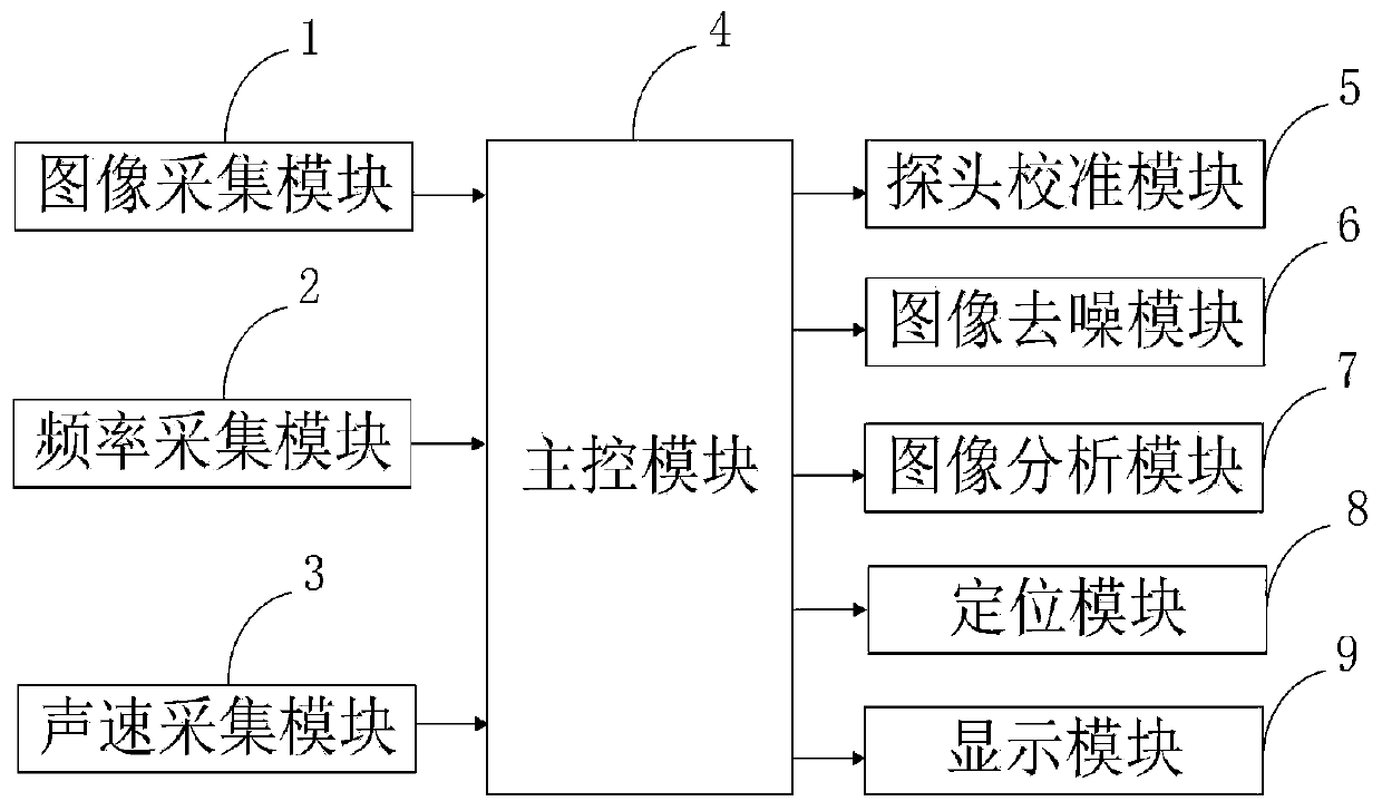
[0071] The calibration method of the probe calibration module 5 provided by the present invention includes:

[0072] 1) Obtaining the blind area of ​​the ultrasonic probe at a preset detection depth by means of detection equipment.

[0073] 2) Place the ultrasonic probe under a three-dimensional magnetic field, and obtain the first imaging image obtained when the ultrasonic probe scans the air, when the acoustic lens of the ultrasonic probe touches the top of the free sensor coated with couplant The obtained second image. Wherein, the color values ​​of the first imaging image and the second imaging image are the same.

[0074] 3) Select any two arcs in the second imaging image as the initial arc and the concentric arc respectively, and calculate the center coordinates, radius and arc of the initial arc and the concentric arc respectively The pixel coordinates on .

[0075] 4) Obtaining the first color difference ratio of the pixel point color value of the starting arc and a...

Embodiment 2

[0080] Image denoising module 6 denoising method provided by the present invention comprises:

[0081] (1) Determine the initial grayscale value of the real image and the initial grayscale value of the speckle image based on the total variation image denoising model of the ultrasonic image through an image processing program.

[0082] (2) Based on the minimization model of the ultrasonic image, iteratively estimate the initial gray value of the real image and the initial gray value of the speckle image respectively, when the estimated gray value of the real image and When the estimated gray value of the speckle image meets the preset convergence condition, the estimated gray value of the real image and the estimated gray value of the speckle image are obtained. A denoised ultrasonic image is generated according to the estimated gray value of the real image.

[0083] The minimization model based on the ultrasonic image provided by the present invention performs iterative estim...


PUM


Abstract

The invention belongs to the technical field of ultrasonic probes, and discloses an accurate positioning machine suitable for a high-frequency ultrasound probe and a control method. The accurate positioning machine suitable for a high-frequency ultrasound probe comprises an image collecting module, a frequency collecting module, a sound speed collecting module, a main control module, a probe calibrating module, an image denoising module, an image analysis module, a positioning module and a display module. According to the accurate positioning machine suitable for a high-frequency ultrasound probe disclosed by the invention, through the probe calibrating module, the calibration process is simplified, and during test, the deviation of a correction value obtained by the ultrasonic probe is low, the stability is good, and in the positioning calculation of each imaging image, an operator adds the correction value, so that the calculated result is more accurate; and besides, through the image denoising module, the denoised ultrasonic images can reserve details and edge part of original ultrasonic images, and have favorable uniformity, and the denoised ultrasonic images can accurately present the tissue structure after ultrasonic treatment.

Description

technical field [0001] The invention belongs to the technical field of ultrasonic probes, and in particular relates to a precise positioner and a control method suitable for high-frequency ultrasonic probes. Background technique [0002] An ultrasonic probe is a device that emits and receives ultrasonic waves during ultrasonic testing. The performance of the probe directly affects the characteristics of the ultrasonic wave and affects the detection performance of the ultrasonic wave. The probe used in ultrasonic testing is a transducer that uses the piezoelectric effect of materials to convert electrical energy and acoustic energy. The key component in the probe is the wafer, which is a single crystal or polycrystalline sheet with piezoelectric effect, and its function is to convert electric energy and acoustic energy into each other. However, manual probe calibration is required for the use of existing ultrasonic probes, which is not only tedious and time-consuming, but a...

Claims


Application Information

Patent Timeline
Patent Type & Authority Applications(China)
IPC IPC(8): A61B8/00
CPCA61B8/4411A61B8/4444A61B8/5215
Inventor 吕启凤孙慧吉晓丽马晓军
Owner THE AFFILIATED HOSPITAL OF QINGDAO UNIV
Why Eureka
Try Eureka