Fuel cylinder block cleaning device

A technology for cleaning devices and cylinders, applied in the directions of cleaning hollow objects, cleaning methods and utensils, chemical instruments and methods, etc., can solve the problems of idling jitter, fuel consumption, weak acceleration, poor cleaning effect, etc., so as to ensure normal use and ensure scraping. Removal effect, effect of increasing contact area

Inactive Publication Date: 2019-08-20
王治军
View PDF7 Cites 9 Cited by
  • Summary
  • Abstract
  • Description
  • Claims
  • Application Information

AI Technical Summary

Problems solved by technology

[0002] Automobile fuel cylinders are roughly divided into in-cylinder direct injection and fuel direct injection from the working principle. The disadvantage of in-cylinder direct injection technology is that after long-term use, it will form carbon deposits in the intake manifold. After carbon deposits in the intake manifold, it will Carbon deposits are generated on the intake valve. The existence of carbon deposits will cause problems such as difficulty in starting the car, weak acceleration, idling vibration, and increased fuel consumption. The current common method is to use fuel cleaner, add it to the fuel tank when refueling, It will have a cleaning effect when it works again, but the cleaning effect of this method is poor when it is used for fuel cylinders with serious carbon deposits. The peculiarity of the shape, simple flushing and brushing with a cleaning tool cannot adequately remove the carbon deposits on the walls of the intake manifold

Method used


Image

  • Fuel cylinder block cleaning device
  • Fuel cylinder block cleaning device
  • Fuel cylinder block cleaning device

Examples


Embodiment Construction

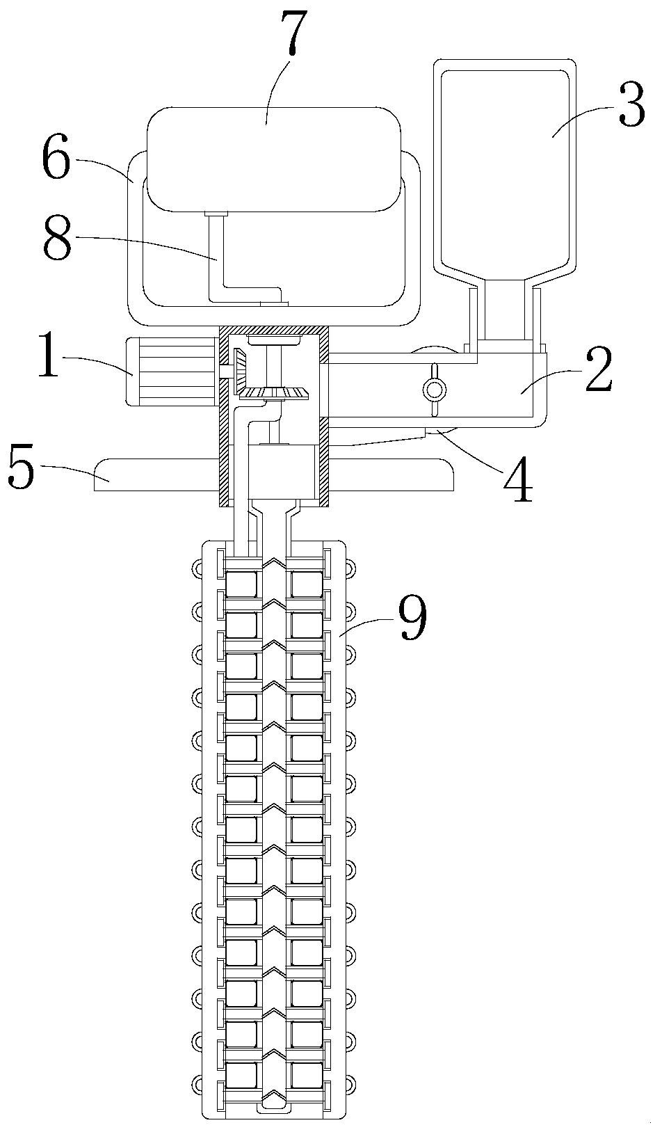
[0024] see Figure 1-4 , the present invention provides a technical solution: a fuel cylinder cleaning device, including a driving mechanism 1, a handle 6, an air bag 7, an air pipe 8 and a cleaning mechanism 9, and the middle part of the bottom of the handle 6 is fixedly connected to the driving mechanism 1 The top of the air bag 7 is fixedly installed in the middle part of the top of the handle 6, and the air outlet of the air bag 7 is connected and communicated with the top of the air delivery pipe 8, and the bottom end of the air delivery pipe 8 runs through the top of the driving mechanism 1 and extends to the driving mechanism 1, the cleaning mechanism 9 is fixedly installed below the drive mechanism 1.

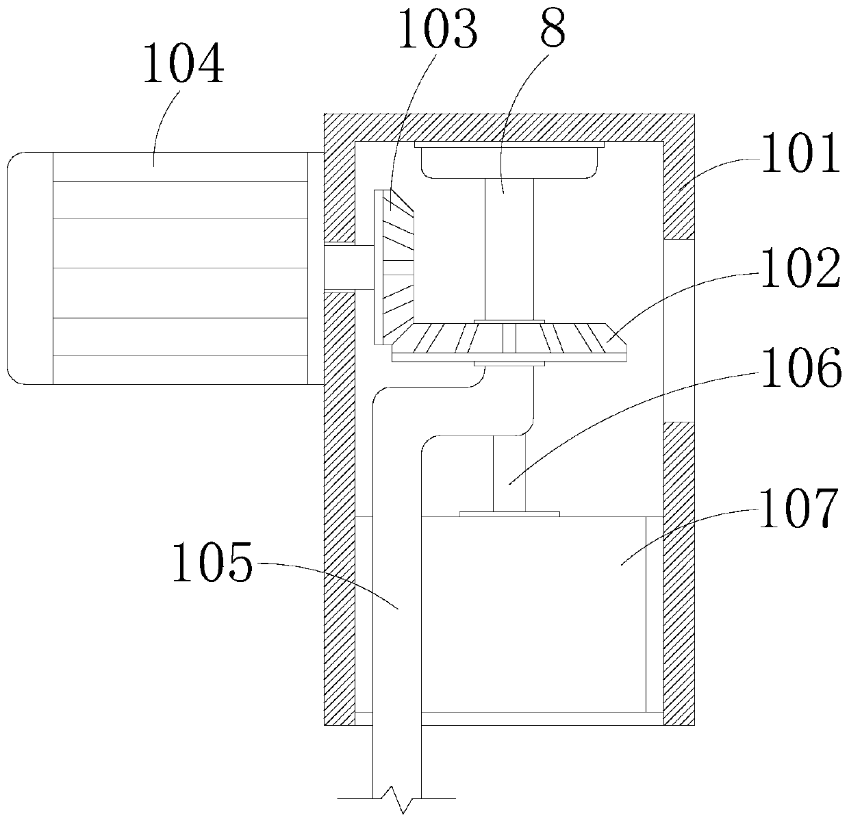
[0025] The driving mechanism 1 includes a fixed block 101, a transverse bevel gear 102, a longitudinal bevel gear 103, a drive motor 104, a bending pipe 105, a connecting rod 106 and a liquid collection pipe 107, and the gas delivery pipe 8 runs through a section in the...


PUM


Abstract

The invention discloses a fuel cylinder block cleaning device, and relates to the technical field of fuel cylinder cleaning. The fuel cylinder block cleaning device comprises a driving mechanism, a holding handle, an inflation bag, a gas transmission pipe and a cleaning mechanism; the middle part of the bottom of the holding handle is fixedly connected to the top of the driving mechanism; the inflation bag is fixedly mounted in the middle part of the top of the holding handle; an exhaust port of the inflation bag is connected with and communicates with the top end of the gas transmission pipe;the bottom end of the gas transmission pipe penetrates through the top of the driving mechanism, and extends into the driving mechanism; and the cleaning mechanism is fixedly mounted under the driving mechanism. The fuel cylinder block cleaning device discharges cleaning liquid into the cleaning mechanism through the driving mechanism, drives the cleaning mechanism to rotate through the driving mechanism to discharge the cleaning liquid, can perform rotary brushing when the cleaning liquid is uniformly coated on the walls of intake manifolds, effectively removes accumulated cartons attached in the intake manifolds, and guarantees normal use of fuel cylinders.

Description

technical field [0001] The invention relates to the technical field of fuel cylinder cleaning, in particular to a fuel cylinder cleaning device. Background technique [0002] Automobile fuel cylinders are roughly divided into in-cylinder direct injection and fuel direct injection from the working principle. The disadvantage of in-cylinder direct injection technology is that after long-term use, it will form carbon deposits in the intake manifold. After carbon deposits in the intake manifold, it will Carbon deposits are generated on the intake valve. The existence of carbon deposits will cause problems such as difficulty in starting the car, weak acceleration, idling vibration, and increased fuel consumption. The current common method is to use fuel cleaner, add it to the fuel tank when refueling, It will have a cleaning effect when it works again, but the cleaning effect of this method is poor when it is used for fuel cylinders with serious carbon deposits. The peculiarity ...

Claims


Application Information

Patent Timeline
Patent Type & Authority Applications(China)
IPC IPC(8): B08B9/051
CPCB08B9/051
Inventor 王治军
Owner 王治军
Why Eureka
Try Eureka