
Full-automatic 3D printing system based on gantry type variable dimensions

A 3D printing and variable size technology, applied in the field of 3D printing, can solve problems such as inability to adapt to printing conditions, limited printing range, and single form of material printing, and achieve the effect of expanding the scope of practical application, expanding the scope, and increasing the printing size.

Inactive Publication Date: 2019-08-20
XIAN UNIV OF TECH
View PDF7 Cites 1 Cited by
  • Summary
  • Abstract
  • Description
  • Claims
  • Application Information

AI Technical Summary

Problems solved by technology

[0002] At present, the working structure of traditional 3D printers is mostly a space-orthogonal structure, and the form of material printing and forming is relatively simple, and the printing method of plane layering is mostly used to realize the printing work of the entire printed part.
At the same time, the movement form of the nozzle in the traditional 3D printer is that three independent servo motors drive the orthogonal ball screw movement in the three-dimensional space, and the printing movement of the nozzle is realized by the movement of the ball screw seat. Its main mechanical structure is three There are two orthogonal linear cylindrical guide rails, but there must be displacement restrictions at both ends of the linear motion structure along the linear guide rail, so that the printing range of traditional 3D printers is limited, so that traditional 3D printers cannot adapt to more printing conditions.

Method used


Image

  • Full-automatic 3D printing system based on gantry type variable dimensions
  • Full-automatic 3D printing system based on gantry type variable dimensions
  • Full-automatic 3D printing system based on gantry type variable dimensions

Examples


Embodiment Construction

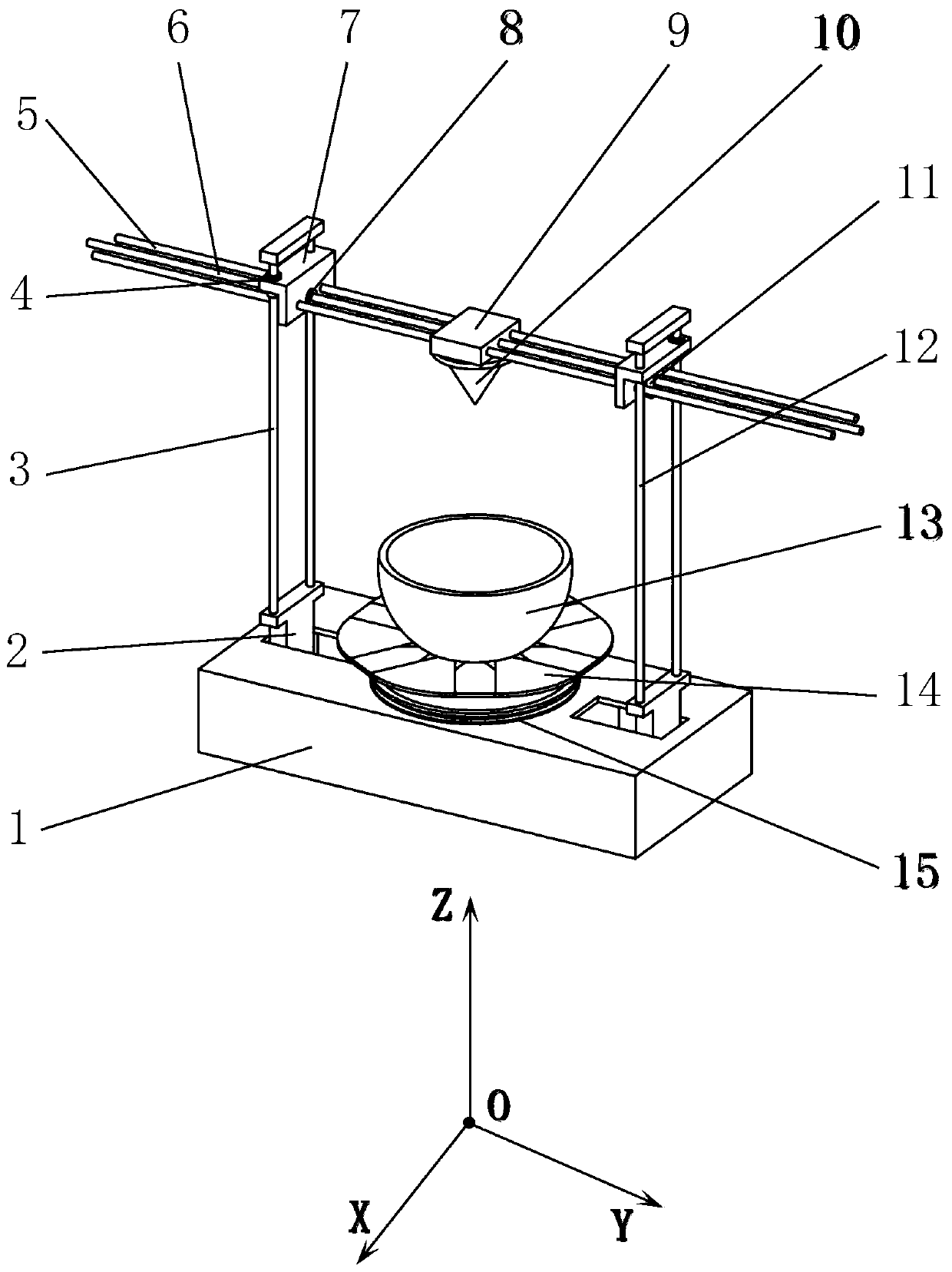
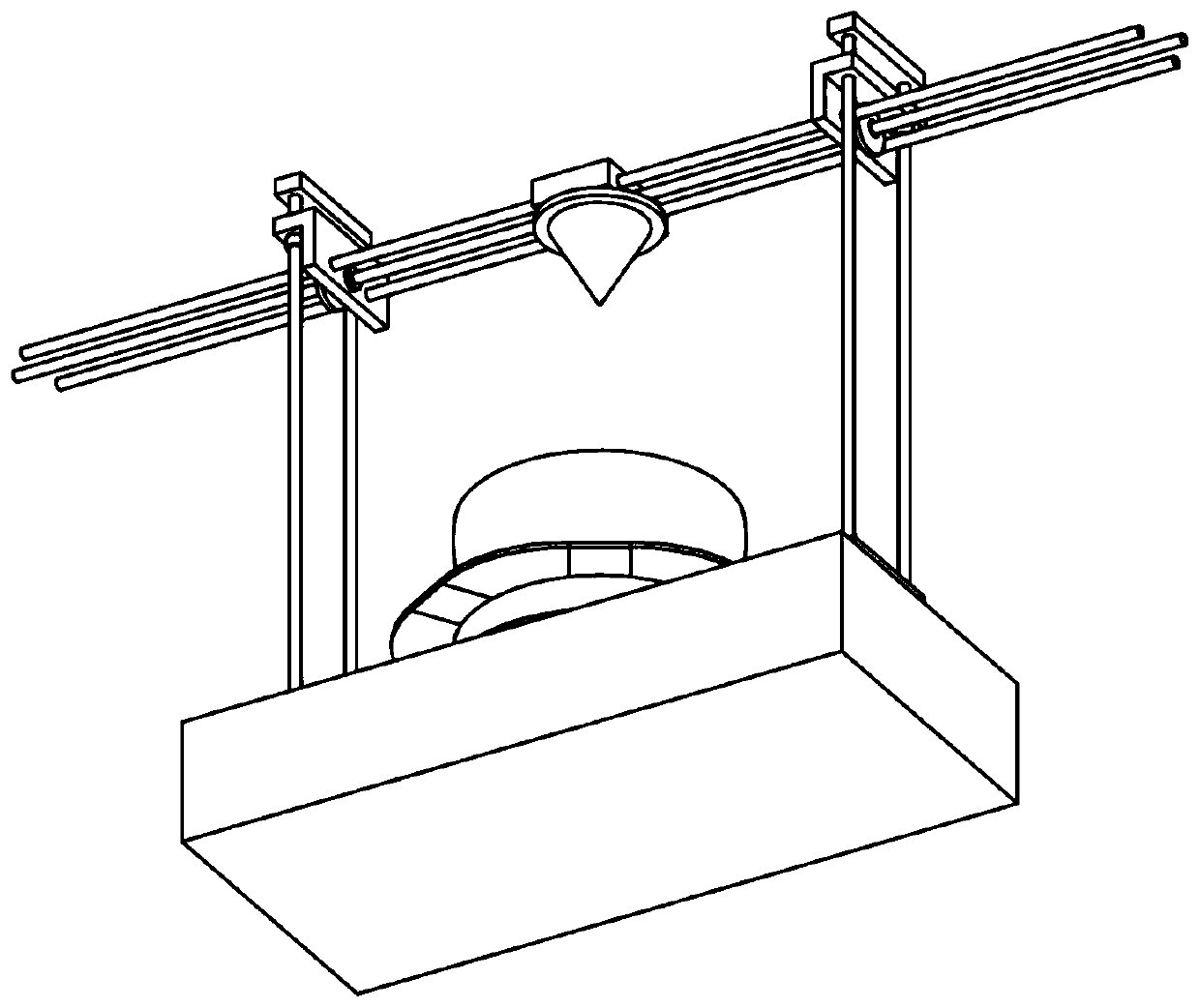
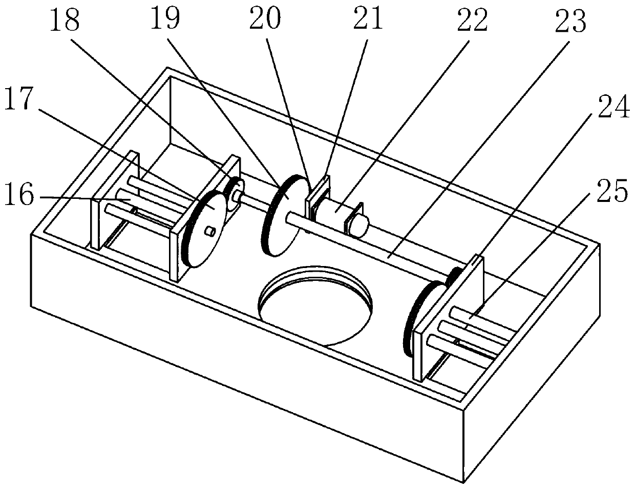
[0029] The structural principle and working principle of the present invention will be further described in detail below in conjunction with the accompanying drawings.

[0030] see Figure 1-7 , based on a gantry-type variable-size automatic 3D printing system, including a base 1, characterized in that a pair of symmetrical through grooves are respectively provided on both sides of the top surface of the base 1, and a vertical rod seat 2 is arranged in the groove; the vertical rod A ball screw a3 and a cylindrical guide rail b12 are respectively provided on the left and right sides of the top of the seat 2; the ball screw a3 passes through the connecting seat 7 and is connected with the ball screw seat a4; the lower part of the connecting seat 7 is provided with three horizontal through holes, two A cylindrical guide rail a5 is provided in the through holes on both sides of the connecting seat 7; a ball screw b6 is provided in the through hole in the middle of the two connecti...


PUM


Abstract

The invention provides a full-automatic 3D printing system based on gantry type variable dimensions. The both sides of the top surface of a base are provided with a pair of symmetrical through slots separately, and each slot is internally provided with a vertical rod seat; the right and left sides of each vertical rod seat are provided with a ball screw a and a cylindrical guide rail b separately;the ball screw a penetrates through connecting seats, and is connected with a ball screw seat a; the lower part of each connecting seat is provided with three horizontal through holes, and the through holes in the both sides of each connecting seat are each provided with a cylindrical guide rail a internally; the through holes in the middle of each connecting seat is internally provided with a ball screw b; the connecting ends of the four cylindrical guide rails between the two connecting seats, and the connecting ends of the two ball screws b are connected with a nozzle seat simultaneously;the lower part of the nozzle seat is provided with a nozzle; and a rotatable platform is arranged at the position, below the nozzle, of the base, and the upper part of the rotatable platform is provided with a scalable printing platform.

Description

technical field [0001] The invention belongs to the technical field of 3D printing, and in particular relates to a fully automatic 3D printing system based on a gantry type variable size. Background technique [0002] At present, the working structure of traditional 3D printers is mostly a space-orthogonal structure, and the form of material printing and forming is relatively simple, and the printing method of plane layering is mostly used to realize the printing work of the entire printed part. At the same time, the movement form of the nozzle in the traditional 3D printer is that three independent servo motors drive the orthogonal ball screw movement in the three-dimensional space, and the printing movement of the nozzle is realized by the movement of the ball screw seat. Its main mechanical structure is three There are two mutually orthogonal linear cylindrical guide rails, but there must be displacement restrictions at both ends of the linear motion structure along the l...

Claims


Application Information

Patent Timeline
Patent Type & Authority Applications(China)
IPC IPC(8): B29C64/227B29C64/245B29C64/20B33Y30/00
CPCB33Y30/00B29C64/20B29C64/227B29C64/245
Inventor 王庚祥韦凯鹤刘超
Owner XIAN UNIV OF TECH
Learn More