
Rib ring type extendable shear type ring supporting cable dome structure

A cable dome and ring bracing technology, which is applied to roofs, building components, building structures, etc., can solve the problems of high construction requirements, waste of materials, and increase the burden of supporting structures, so as to reduce the difficulty of construction technology, improve stability, and improve economic effect

Inactive Publication Date: 2019-08-20
SOUTHEAST UNIV
View PDF6 Cites 6 Cited by
  • Summary
  • Abstract
  • Description
  • Claims
  • Application Information

AI Technical Summary

Problems solved by technology

[0004] The traditional cable dome structure has some disadvantages: (1) The construction mechanism of the cable dome structure is relatively complicated, the construction is difficult, and the construction requirements are high, resulting in few large-span cable dome projects built in China
(2) The traditional cable dome structure only has a single vertical strut and the stability outside the radial plane is weak, and the compression rods are not connected, so the stability of the compression rods is poor
(3) The pressure of the edge ring beam is high, resulting in an increase in the cross-sectional area of ​​the edge ring beam, which increases the burden on the supporting structure and wastes materials

Method used


Image

  • Rib ring type extendable shear type ring supporting cable dome structure
  • Rib ring type extendable shear type ring supporting cable dome structure
  • Rib ring type extendable shear type ring supporting cable dome structure

Examples


Embodiment Construction

[0026] The present invention will be further explained below in conjunction with the accompanying drawings and specific embodiments. It should be understood that the following specific embodiments are only used to illustrate the present invention and are not intended to limit the scope of the present invention. It should be noted that the words "front", "rear", "left", "right", "upper" and "lower" used in the following description refer to the directions in the drawings, and the words "inner" and "outer ” refer to directions towards or away from the geometric center of a particular part, respectively.

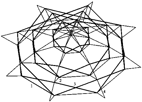
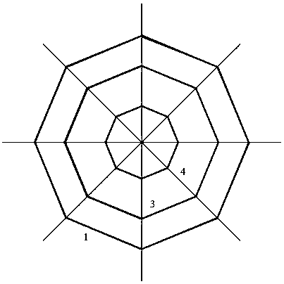
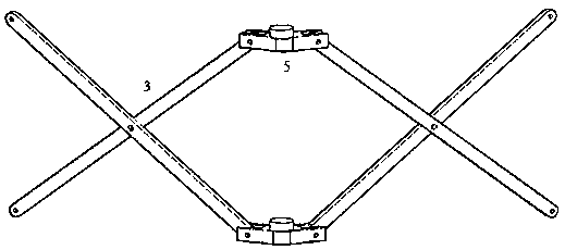
[0027] A kind of rib-ring type expandable scissor ring-supported cable dome structure according to the present invention, see figure 1 , the extendable scissor hinge struts 3 are arranged continuously in the ring direction, that is, the horizontal projection coincides with the ring cable 1. The upper ends of the extendable scissor hinge strut 3 and the oblique cable 2 are hing...


PUM


Abstract

The invention discloses a rib ring type extendable shear type ring supporting cable dome structure. The rib ring type extendable shear type ring supporting cable dome structure comprises ring cables,stay cables, extendable shear type hinge supporting rods and dorsal cables. According to the novel structure, incontinuous supporting rods in a traditional rib ring type cable dome are replaced with the continuous extendable shear type hinge supporting rods, the supporting rods are continuously arranged in the circumferential direction, and the horizontal projections of the supporting rods coincide with the ring cables. The upper ends of the supporting rods and the stay cables are in hinged connection with the dorsal cables, the inner stay cables and the outer stay cables are hinged to the upper ends and the lower ends of the adjacent shear type hinge supporting rods separately, the ring cables are hinged to the lower ends of the continuous supporting rods on the same rings, and closed arrangement is achieved. By means of prestress tensioning, prestress is established in the dorsal cables, the ring cables and the stay cables, and the structure belongs to an all-tension structure system. Compared with a traditional cable dome structure, the rib ring type extendable shear type ring supporting cable dome structure has good stability performance outside the radial plane, high construction efficiency and good comprehensive economic benefits. The rib ring type extendable shear type ring supporting cable dome structure is suitable for roofs of large-span buildings and suitable for sports buildings and exhibition buildings, and is in a prestress large-span space structural style with broad development prospects.

Description

technical field [0001] The invention discloses a brand-new full-tension structure, relates to a rib-ring type expandable scissor-type hoop cable dome structure, and belongs to the technical field of civil engineering space structures. Background technique [0002] The prestressed structure has experienced the course of its birth, growth and development and maturity, and has become a common and widely used conventional, efficient and advanced practical structural form in the design of civil engineering structures. With the development of the economy and the growth of social demand, engineers have proposed new structural forms derived from the combination of prestressing technology and steel structure systems, such as string beams, cable nets, prestressed trusses, suspension domes, cable domes, etc. to meet these needs. The prestressed steel structure greatly enriches the architectural shape, improves the bearing capacity of the structure, reduces the deformation and reduces ...

Claims


Application Information

Patent Timeline
IPC IPC(8): E04B7/08E04B7/14E04B1/343E04B1/344
CPCE04B7/08E04B7/14E04B1/3441E04B1/3449
Inventor 陆金钰王淑婷陆鼎
Owner SOUTHEAST UNIV
Learn More