
Oil drain device of reciprocating pump

A technology of reciprocating pumps and oil drainers, which is applied in wellbore/well components, earthwork drilling, sealing/package, etc., which can solve the problem of high cost of use, oil drainers that cannot drain oil, and are not reusable and other issues, to achieve the effect of loose operating conditions and loose requirements

Pending Publication Date: 2019-08-20
LIAONING XINHUA INSTR CO LTD
View PDF0 Cites 0 Cited by
  • Summary
  • Abstract
  • Description
  • Claims
  • Application Information

AI Technical Summary

Problems solved by technology

The main problem in the use of this oil drainer is: before realizing the oil draining function, the piston of the oil pump must be taken out of the well, otherwise the oil draining operation cannot be performed, so the requirements for the operating conditions are relatively strict; in addition , after completing an oil draining operation, the oil drainer is completely scrapped and must be replaced, that is to say, it does not have a reusable function, so the cost of use is high; moreover, there are many accidents due to throwing heavy objects, such as oil The fluid is viscous or clogged, heavy objects are not easy to cut the shear nails, and the oil drainer cannot drain oil

Method used


Image

  • Oil drain device of reciprocating pump
  • Oil drain device of reciprocating pump
  • Oil drain device of reciprocating pump

Examples


Embodiment Construction

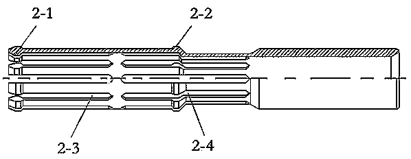
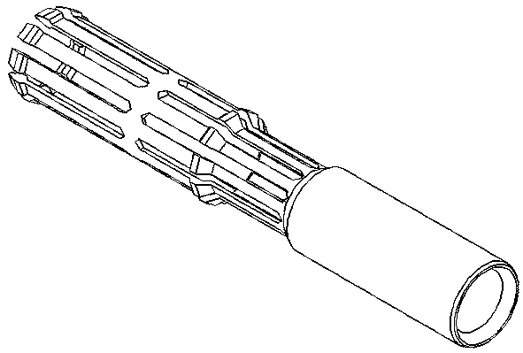
[0009] See Figure 1-3 The specific structure is as follows: the upper end of the upper joint 1 is provided with an internal thread for connecting the oil pipe, the upper outer sleeve 3 is threadedly connected with the lower end of the upper joint 1 and a sealing ring 7 is added, the upper inner diameter of the upper outer sleeve 3 is processed with a card groove A, and the lower inner diameter of the upper outer sleeve 3 is processed with a Slot B; the jaw 2 is milled with two sections of 10 equal gaps 8-1, 8-2 to make it flexible; the upper end of the jaw 2 is provided with an inner and outer boss 2-1, and the middle of the jaw 2 is provided with an outer protrusion Platform 2-2; claw 2 is placed inside the upper jacket 3, and the inner and outer bosses 2-1 on the upper end of the claw 2 are placed in the slot A of the upper jacket 3; the upper jacket 3 and the lower joint 6 are threaded to connect the lower jacket 5. Oil drain hole C is processed on the lower casing 5; a se...


PUM


Abstract

The invention provides an oil drain device of a reciprocating pump. The oil drain device comprises an upper connector, an upper jacket, clamping jaws, a lower connector and a sliding connecting rod. The oil drain device of the reciprocating pump is characterized in that a clamping groove is formed on the inner diameter of the upper portion of the upper jacket, and a clamping groove is formed on the inner diameter of the lower portion of the upper jacket; two equal notches are milled on each clamping jaw, the upper end of the clamping jaw is provided with an inner and outer boss, and the middleportion of the clamping jaw is provided with an outer boss; the clamping jaws are located inside the upper jacket; the outer bosses of the upper ends of the clamping jaws are located in the clampinggroove of the upper jacket; a lower jacket is in threaded connection between the upper jacket and the lower connector; the lower jacket is provided with oil drain holes; a sealing gasket is arranged at the gap between the upper jacket and the lower ends of the clamping jaws; a rubber pad is vulcanized in an inner pore of the upper end of the lower connector; the sliding connecting rod is arrangedinside the clamping jaws; and the upper end and the lower end of the sliding connecting rod are provided with an internal thread and an external thread connected with sucker rods correspondingly. Theoil drain device of the reciprocating pump has loose requirements for using and operating conditions and can be repeatedly used.

Description

technical field [0001] The invention relates to a downhole tool used for oil field workover operations, in particular to a reciprocating pump upper drainer. Background technique [0002] There are two ways to use and install the existing oil drainer, one is installed between the upper end of the pump barrel of the oil well pump and the lower end of the oil well pipe, and the other is installed between the lower end of the pump barrel of the oil well pump and the fixed valve of the pump. between the upper ends of the hood. During the workover operation, the oil drainage operation process of the oil drainer is: firstly take out the sucker rod and the piston from the well; To achieve the purpose of oil drainage. The main problem in the use of this kind of oil drainer is: before realizing the oil draining function, the piston of the oil pump must be taken out of the well, otherwise the oil draining operation cannot be performed, so the requirements for the operating conditions...

Claims


Application Information

Patent Timeline
IPC IPC(8): E21B34/12
CPCE21B34/12
Inventor 梁伟成梁闯
Owner LIAONING XINHUA INSTR CO LTD
Learn More