a concentrator

A light concentrator and light collection technology, which is applied in the direction of instruments, optics, and condenser mirrors, can solve the problems of high production and material costs, energy consumption, and consumption, and achieve reduced production costs, improved light collection effects, and strong light collection effects Effect

Active Publication Date: 2021-06-25
JIANGSU RUIJING INST OF OPTO ELECTRONICS CO LTD +2
View PDF0 Cites 0 Cited by
  • Summary
  • Abstract
  • Description
  • Claims
  • Application Information

AI Technical Summary

Problems solved by technology

[0003] At present, traditional concentrators are mainly divided into active concentrators and passive concentrators. The active concentrator is to install a sun tracking system on the concentrator, which can change the angle of the concentrator according to the azimuth of the sun. , to increase the efficiency of light collection, but additional power is needed to supply the light collector to move, which consumes energy, which is contrary to the concept of environmental protection and energy saving. The traditional passive light collector not only has low light collection efficiency, but also is too large and requires a lot of energy. High production and material costs, and inconvenient both for transportation and installation

Method used


Image

  • a concentrator
  • a concentrator
  • a concentrator

Examples


Embodiment

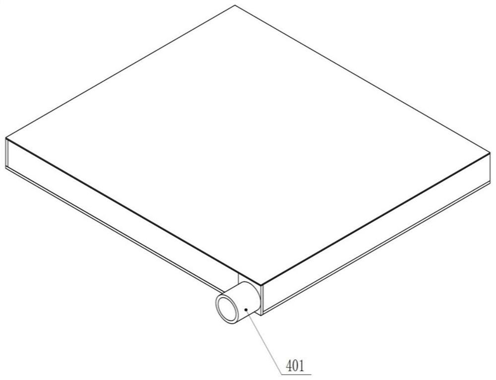
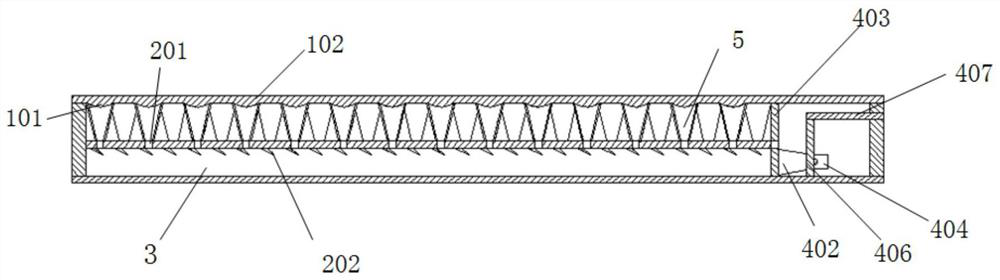
[0048] A light collector, comprising: a lens array plate 1, a light collecting hole array plate 2, a light guide groove 3 and a lateral light collecting system;

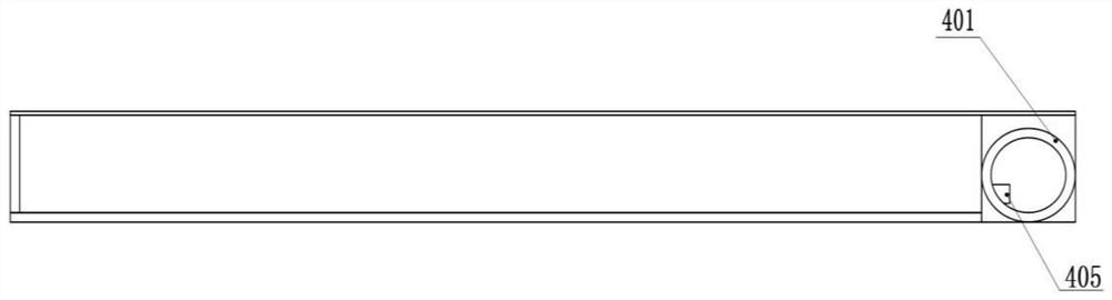
[0049]The light guide groove 3 is provided with a light collecting hole array plate 2, the bottom of the light collecting hole array plate 2 is provided with a first-level reflector 202, the lateral light collecting system is arranged on one side of the light guide groove 3, and the lens array plate 1 is installed on the guide groove 3. Above the light groove 3 , an integral closed structure is formed with the light guide groove 3 .

[0050] Furthermore, the light collector also includes a conical array plate 5 ; the conical array plate 5 is arranged between the light collecting hole array plate 2 and the lens array plate 1 .

[0051] Further, the lens array plate 1 includes a lens 101 and a lens array flat plate 102;

[0052] The lenses 101 are arranged at the bottom of the lens array plate 102 in an array arrangem...


PUM


Abstract

The invention discloses a light collector, comprising: a lens array plate, a light collecting hole array plate, a light guide groove and a side light collecting system; The bottom of the hole array plate is provided with a primary reflector, the side light collection system is arranged on one side of the light guide groove, the lens array plate is installed above the light guide groove, and forms a One-piece closed structure. In the present invention, the light is irradiated into the light-collecting hole array plate through the lens array plate, and the light is reflected one by one by the reflector on the light-collecting hole array plate, and transmitted to the side light collecting system. Finally, the present invention can Integrating all the light incident from the lens array plate into one beam produces a very strong light collection effect, and the invention has a simple structure, reduces the production cost, reduces the volume of the light collector, and is more convenient to install.

Description

technical field [0001] The present invention relates to the technical field of light collection, and more particularly to the technical field of light collection. Background technique [0002] As the earth's resources become increasingly scarce, the investment cost of basic resources is increasing, and the problems of resource waste and environmental pollution have been paid more and more attention. Solar energy has become one of the new energy sources with the most development potential. Therefore, in order to improve the The utilization rate of energy, the concentrator came into being. [0003] At present, traditional concentrators are mainly divided into active concentrators and passive concentrators. Active concentrators are equipped with a sun-chasing system on the concentrator, which can change the angle of the concentrator according to the orientation of the sun. , increase the efficiency of light collection, but it needs extra power to supply the collector to move, ...

Claims


Application Information

Patent Timeline
Patent Type & Authority Patents(China)
IPC IPC(8): G02B19/00
CPCG02B19/0004G02B19/0042
Inventor 刘俭刘辰光李亮王宇航王伟波陈刚
Owner JIANGSU RUIJING INST OF OPTO ELECTRONICS CO LTD
Why Eureka
Try Eureka